18
Installation (cont.)
Servo, Throttling & Boost Valves (cont.)
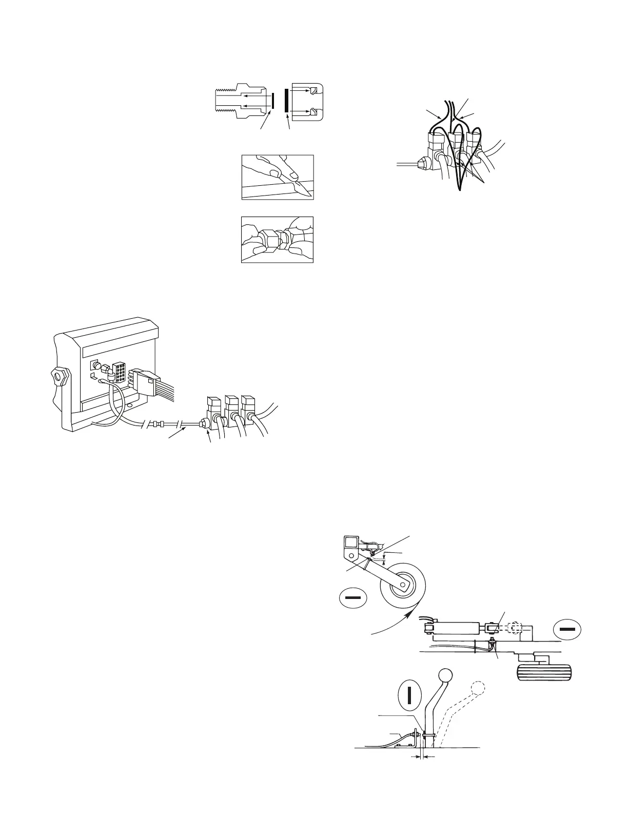
1. Disassemble fittings and replace
“O” rings with those supplied.
Insert snubber washer into male
fitting.
2. Measure length and cut tubing
at slight angle for easy insertion.
3. Loosen nut on fitting until 3
threads are visible.
4. Moisten end of tubing and
insert straight into fitting until
it bottoms out. Tighten nut by
hand.
5. Connect tubing to inlet side
of solenoid valves using
appropriate adapter fittings. Attach elbow fitting to
console. Route tubing along wire harness and secure
with plastic ties.
SNUBBER
WASHER
“O” RINGS
UNION
MALE
FITTING
¼” PRESSURE
LINE TO SPRAYER
REDUCTION FITTING
(NOT SUPPLIED)
FLOW IN
Boom Solenoid Valves
Plumb solenoids with flo-thru port as shown. Solenoids of
different design may require a “T”. Use lines large enough to
minimize pressure drops.
Locate 3’ (1 m) solenoid cable (BLACK cable tie near
connector). Crimp female tab terminal on RED, WHITE
and BLACK wires. Slip red wire onto left boom solenoid,
white onto center and black onto right. To assure a good
connection and avoid corrosion, apply silicone grease to
solenoid lugs.
Make 3 ground wires of appropriate length using 14 Ga.
BLUE wire. Crimp female tab terminal on one end of each
wire and ¼” ring terminal on the other. Slip female terminals
onto solenoid terminals. Bolt ¼” ring terminals to a good
frame round. Secure wires with plastic ties and plug into
main harness cable having BLACK cable tie near connector.
Sensor (Black body)
1/8” to 3/8”
(6 mm to 13 mm)
when wheels are up
Magnet
South
North
1/8” to 3/8 “ (6 mm to 13 mm)
space when equipment is
down and operating
Sensor Cable
(black body)
Magnet
South
North
Run Position
Hold
Position
Run
Position
Hold
Position
Sensor
(Black body)
Magnet
North
South
NOTE: If you are using electric boom solenoids, you may
have to install a light bulb or some other 12 volt load in
place of the solenoids to get the monitor to acknowledge
boom widths and count area.
Optional Remote Run/Hold Installation
The remote Run/hold (shortest cable on the main harness)
option automatically turns the solenoid valves off and stops
the acre accumulation when equipment is raised, such
as turning on end rows. The remote sensor overrides the
console when the master switch is in the AUTO or MANUAL
position. (The remote sensor is the same as the magnetic
speed sensor and has a YELLOW cable tie near the connector.
The basic idea is to attach a magnet to a lever or some part
of the equipment that moves when the implement is raised
and lowered. When the magnet is away from the sensor the
console will be in HOLD and will shut off the solenoid valves
and stop counting acres.
NOTE: The Run/’Hold sensor is 3 feet (1 m) long. You may
require extension cables which are available in 5 ft. (1.5 m),
10 ft. (3 m), 15 ft. 4.5 M) and 20 ft. (6 m) lengths.
You may also use a toggle or other type switch. Simply
cut the BLUE jumper wire in the dust cover and splice on
a appropriate length of wire to reach your switch. When
switch is closed, console is in RUN (provided master switch
is in AUTO or MANUAL). When switch is open, console is in
HOLD.
BLACK
WHITE
RED
BLUE
WIRES
CONNECT TO
FRAME GROUND