Anhydrous Ammonia (cont.)
Flowmeter Cleaning Procedure
NOTE: Cleaning the flowmeter does not require loosening
the pipe thread fittings. The fittings are pressure tested and
precisely adjusted to fit the brackets. Do not disassemble
them. The entire servo/flowmeter assembly is removed
as a single unit, elbows and all. The silver colored fittings
between the elbows and the heat exchanger are unions.
To remove the assembly, loosen the union hex closest to
the heat exchanger. Remove the two U-bolts that hold
the servo/flowmeter assembly to the brackets. Unscrew
the union from the heat exchanger and remove the servo/
flowmeter assembly.
Use running water to rinse the assembly of any accumulated
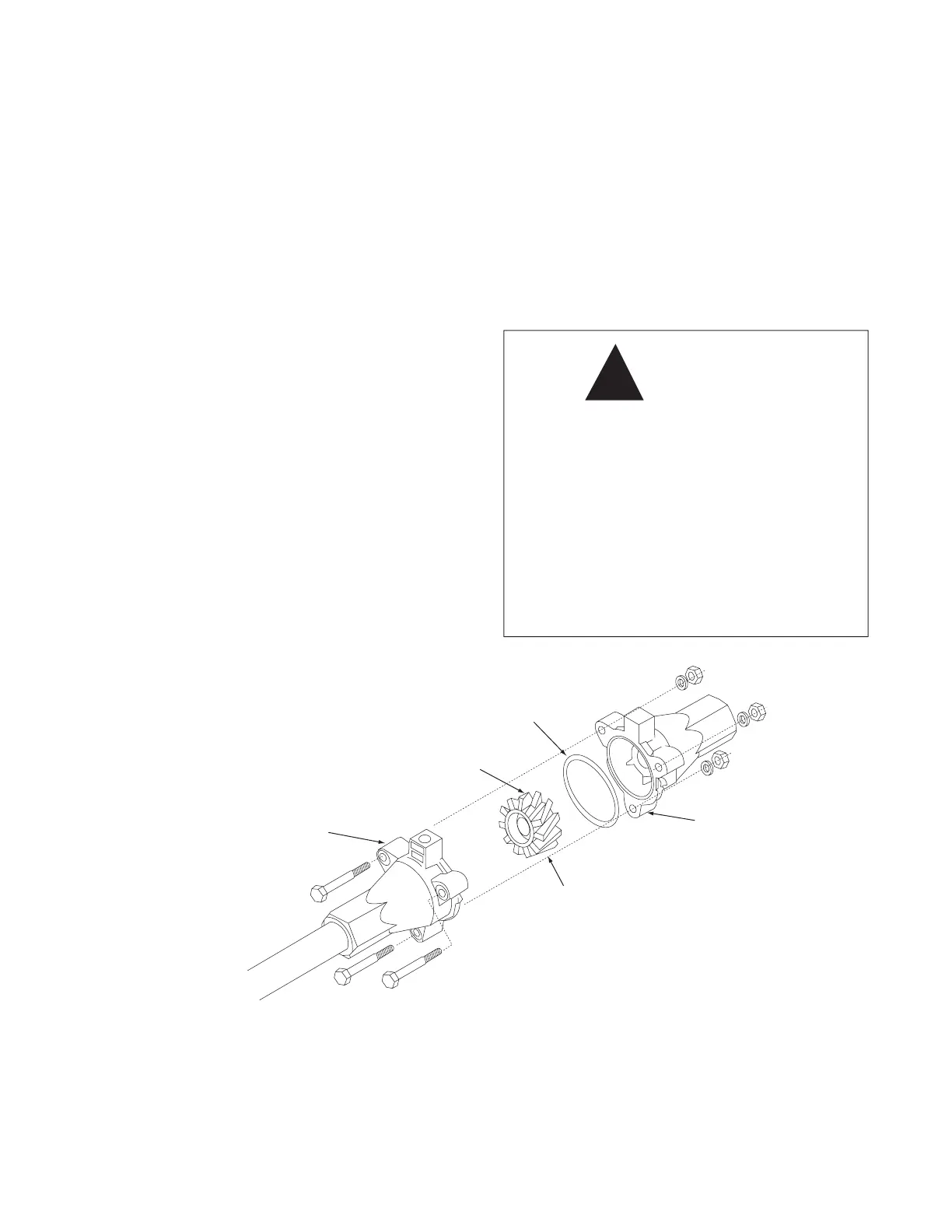
dirt. Remove the three flowmeter bolts, carefully open the
flowmeter and remove the turbine. Thoroughly clean the
turbine and housings of any foreign material (dirt, pieces of
teflon tape, rust on magnets, etc.).
Set and spin the turbine in each flowmeter housing half.
(Turbine goes magnets down in the sensor housing and
magnets up in the non-sensor housing). It should spin freely.
If not, remove the turbine, wipe the shaft and try again.
Place the servo, flowmeter end up, in a vice or other suitable
fixture. Set turbine, magnets up, in non-sensor housing.
(Magnets must line up with hole for sensor). Properly
position gasket on housing. Gasket may be reused as few
times but will eventually need to be replaced). Pipe thread
compound is not absolutely necessary but will insure a good
!
WARNING
Always follow standard safety
procedures and use proper
safety equipment when working
on anhydrous ammonia equipment
Before working on plumbing:
• Disconnect nurse tank.
• Remove all ammonia from system
• Leave all valves on applicator open.
seal. Be careful not to get compound inside flowmeter or
turbine will stall. Carefully put other flowmeter housing
(sensor half) in place. Position the housing so that the two
square lugs are lined up with each other. Drop all three bolts
into holes. Hold lock washers in place and finger tighten
nuts. Making sure gasket is still properly aligned, evenly
tighten all three nuts. Nuts should be torqued to 1 ft./lb.
(1.35 Nm). Attach tag by running wire between a bolt and
the housing and twist.
After assembly, shaking flowmeter end for end should
produce a “rattling” sound (shaft end play).
Start with original calibration number and follow procedure
in manual for verifying flowmeter accuracy.
GASKET
P/N 10137
MAGNETS MUST
FACE SENSOR
HOUSING
TURBINE WITH
2 MAGNETS
P/N 10091
HOUSING WITH
SENSOR RECEPTACLE
INCLUDES BEARING
HOUSING,
INCLUDES
BEARING
43