MCP2221 I
2
C Demonstration Board User’s Guide
DS50002480A-page 12 2016 Microchip Technology Inc.
1.2.2 Other Hardware Features
The board also provides features that are independent of the software application:
• 5V or 3.3V user-selectable V
DD
, up to 500 mA operating capability for the
demonstration board and all on-board devices.
•I
2
C female socket (similar to the PICkit™ Serial Analyzer) for connectivity to exter-
nal slaves, as well as test points for the I
2
C lines, and the option to
disconnect the on-board, 4.7 k
pull-up resistors for the I
2
C data and clock lines.
• In-Circuit Serial Programming™ (ICSP™) male connector to debug or program
the PIC16F1509 using a PICkit 3 programmer or another compatible tool.
• The option to connect the PIC16F1509 device’s Universal Asynchronous
Receiver/Transmitter (UART) to the board’s RS-232 connector (through the
MAX3232 transceiver).
• A small prototyping area which includes extensions of the board’s power (V
DD
)
and ground (GND) lines.
• Test points to measure the current, voltage or power of non-USB devices (as well
as receive configurable interrupts) using the PAC1710 current-sensing chip.
• Option to connect the interrupt pin of the MCP23008 I/O expander to an external
interrupt pin of the PIC16F1509 for custom applications.
1.2.3 I
2
C Devices Available on the Board
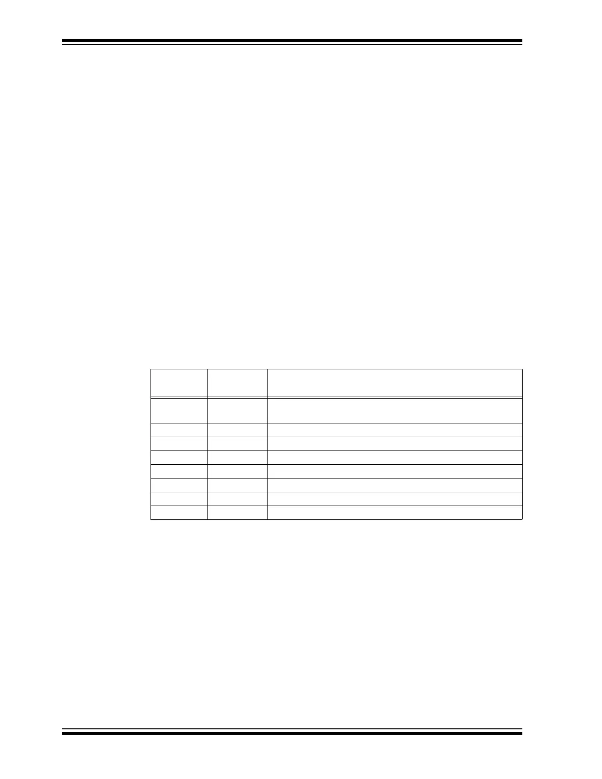
Ta bl e 1- 1 identifies the I
2
C devices (master and slaves) available on the MCP2221 I
2
C
Demonstration Board.
TABLE 1-1: I
2
C DEVICES AVAILABLE ON THE MCP2221 BOARD
Device
Name
I
2
C
Master/Slave
Description
MCP2221 Master USB to I
2
C/UART/SMBus Protocol Converter with GPIO
(Master Mode)
PAC1710 Slave Single High-Side Current Sense Monitor with Power Calculation
24LC128 Slave 128-Kbit EEPROM
MCP9808 Slave Temperature Sensor
MCP3221 Slave 1-Channel, 12-Bit Analog-to-Digital Converter (ADC)
MCP4726 Slave 12-Bit Digital-to-Analog Converter (DAC)
MCP23008 Slave 8-Bit I/O Expander
PIC16F1509 Slave 8-Bit Microcontroller (preprogrammed to perform as I
2
C slave)