USING AN ADAPTER
Use the AC164110 adapter between the MPLAB PICkit 4 In-Circuit Debugger and the target device with the modular
interface (six conductor) cable. The pin numbering for the connector is shown from the bottom of the target PCB in
Figure 3-3.
Figure 3-3. Standard RJ-11 Connection at Target
1
2
3
4
5
6
Target
Connector
Target
Bottom Side
PC Board
VPP/MCLR
Vss
PGC
V
DD
PGD
Reserved
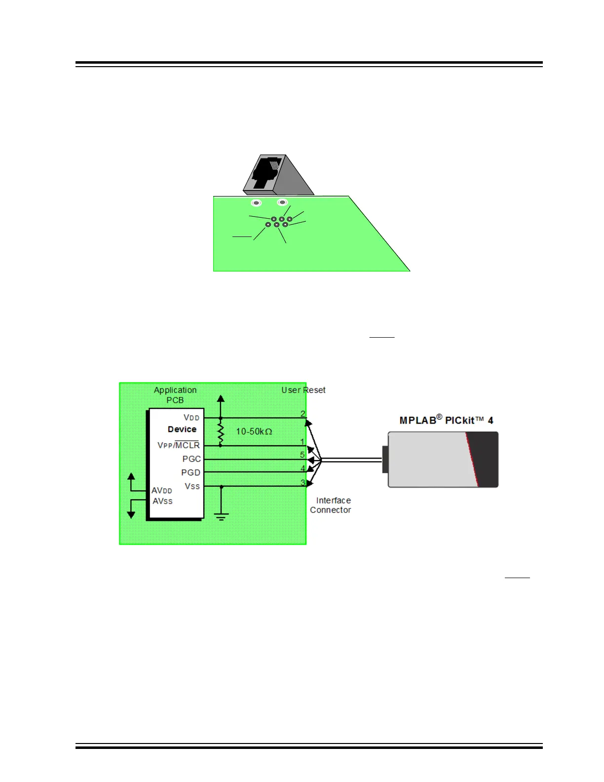
3.2.2 Target Connection Circuitry
Figure 3-4 below shows the interconnections of the MPLAB PICkit 4 In-Circuit Debugger to the connector on the
target board. The diagram also shows the wiring from the connector to a device on the target PCB. A pull-up resistor
(usually around 10-50 kΩ) is recommended to be connected from the V
PP
/MCLR line to V
DD
so that the line may be
strobed low to reset the device.
Figure 3-4. Standard Connection to Target Circuitry
3.2.3 Target Powered
In the following descriptions, only three lines are active and relevant to core debugger operation: pins 1 (V
PP
/MCLR),
5 (PGC), and 4 (PGD). Pins 2 (V
DD
) and 3 (V
SS
) are shown in Figure 3-4 for completeness. MPLAB PICkit 4 has two
configurations for powering the target device: internal debugger and external target power.
The recommended source of power is external and derived from the target application (see figure below). In this
configuration, target V
DD
is sensed by the debugger to allow level translation for the target low voltage operation. If
the debugger does not sense voltage on its V
DD
line (pin 2 of the interface connector), it will not operate.
Operation
© 2020 Microchip Technology Inc.
User Guide
DS50002751D-page 12