Table 4-1. EDBG LED Control
Mode Power LED Status LED
Normal mode The power LED is on when
power is applied to the board.
Activity indicator, the LED flashes
when any communication
happens to the EDBG.
Bootloader mode (idle) The power LED and the status LED blink simultaneously.
Bootloader mode (firmware
upgrade)
The power LED and the status LED blink in an alternating pattern.
For additional information on the EDBG, see the EDBG User Guide.
4.2 Xplained Pro Analog Module (XAM)
4.2.1 Overview
The Xplained Pro Analog Module (XAM) extends the embedded debugger with high dynamic range
current measurement. This enables power profiling of the target system.
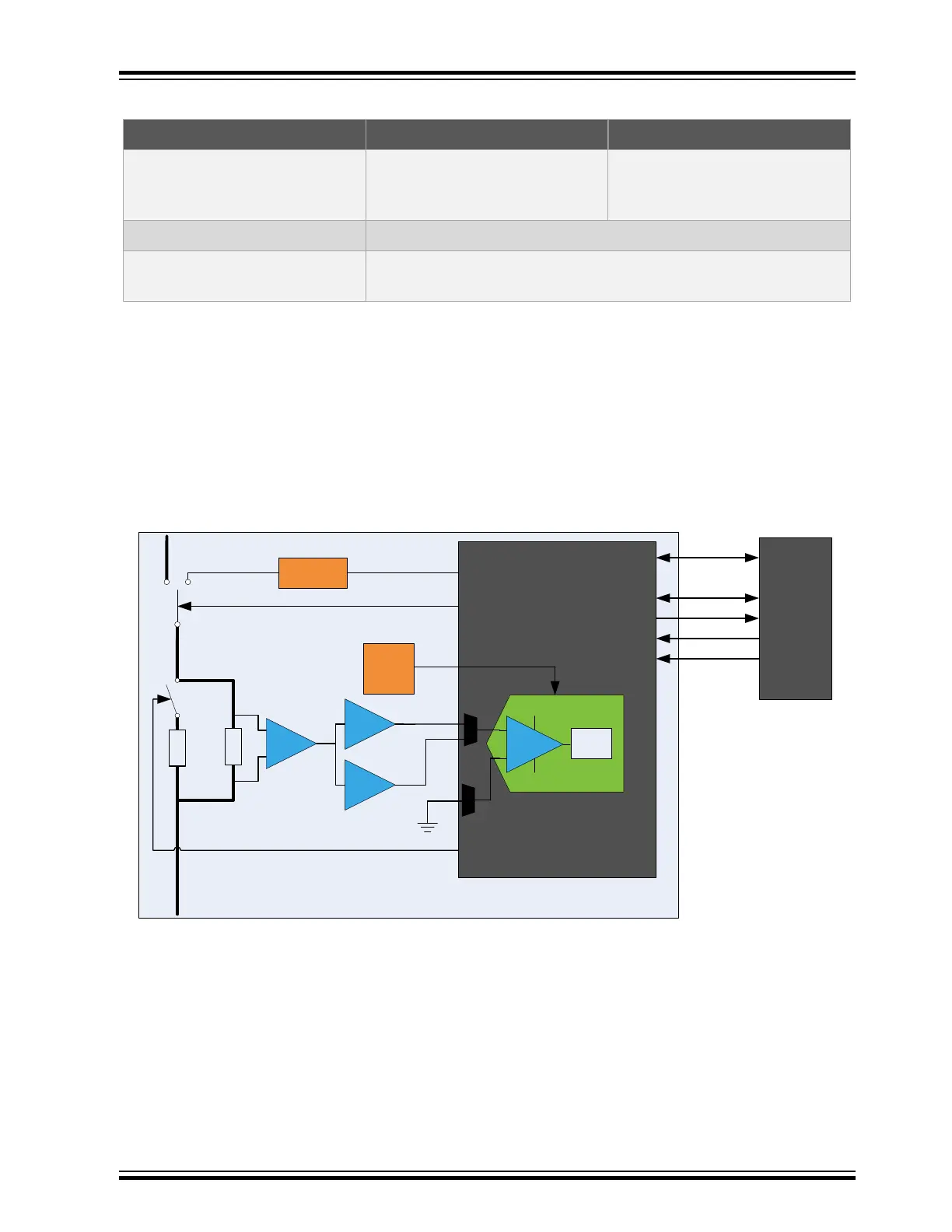
Figure 4-1. XAM Block Diagram
ADC0
ADC1
20x
voltage
reference
2.7V
Control MCU
GND
S&H
ADC
Calibration
circuitry
Calibration ON/OFF
AREF
GPIO
GPIO(s)
GPIO
100 mOhm
100 Ohm
EDBG
SPI
Clock sync
SWD
Sync GPIO
I2C
2x
16x
Current input
Current output
Range selection
Pre-amplifier
Active filter with
gain
Xplained Pro Analog Module (XAM)
20x
The XAM consists of:
• Calibration circuitry
• Voltage reference circuitry
• Analog front-end:
– Shunt resistors with a range selection switch
– Pre-amplifier
– Two active filters with gain
• Control MCU
SAM E54 Xplained Pro
© 2017 Microchip Technology Inc.
DS70005321A-page 10