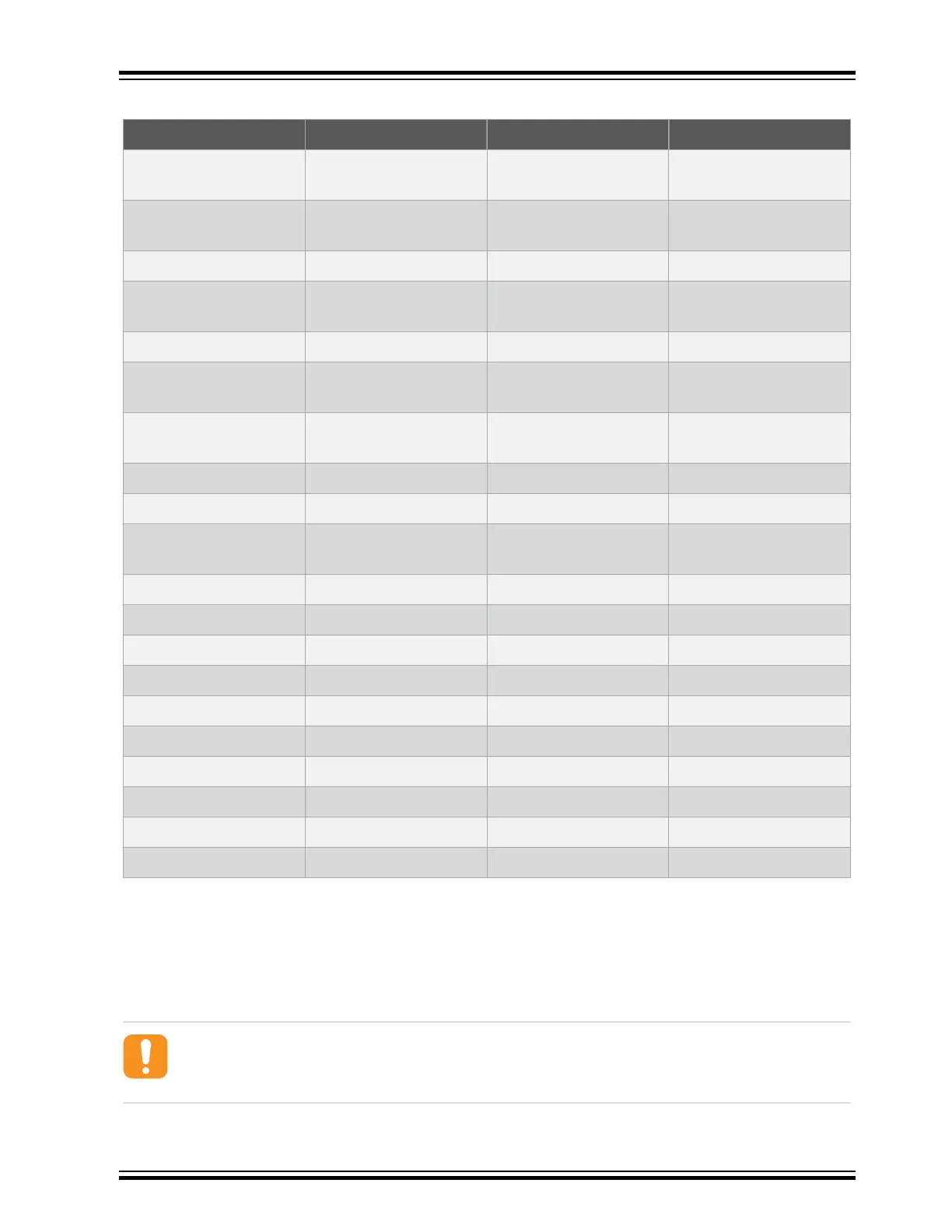
Table 5-11. Cortex Debug + ETM Connector
Pin number Pin/Net Function Shared functionality
1 [VTREF] VCC_TARGET_P3V3 ATSAME54P20A
voltage
2 [TMS/SWDIO] PA31 SWDIO Cortex DBG and EDBG
SWD
3 [GND] GND Ground
4 [TCK/SWCLK] PA30 SWCLK Cortex DBG and EDBG
SWD
5 [GND] GND Ground
6 [TDO/SWO] PB30 SWO Cortex DBG and EDBG
SWD
7 [KEY] - Not connected, the pin is
removed.
8 [TDI] - -
9 [GND] GND Ground
10 [nSRST] RESET_N Reset RST BTN, Cortex DBG,
and EDBG SWD
11 [NC] - -
12 [RTCK/TRACECLK] PC27 TRACECLK
13 [NC] - -
14 [SWO/D0] PC28 TRACEDATA[0]
15 [GND] GND Ground
16 [ntRST/D1] PC26 TRACEDATA[1]
17 [GND] GND Ground
18 [DBGRQ/D2] PC25 TRACEDATA[2]
19 [GND] GND Ground
20 [DBGACK/D3] PC24 TRACEDATA[3]
5.2.10 Current Measurement Header
An angled 1x2, 100-mil pin header marked with the MCU current measurement is located at the upper
edge of the SAM E54 Xplained Pro. All power to the ATSAME54P20A is exclusively routed through this
header (excluding power to headers and peripherals). To measure the power consumption of the device,
remove the jumper and replace it with an ammeter.
Caution: Removing the jumper from the pin header while the kit is powered may cause the
ATSAME54P20A to be powered through its I/O pins. This may cause permanent damage to the
device.
SAM E54 Xplained Pro
© 2017 Microchip Technology Inc.
DS70005321A-page 23