signal is connected to PC19, which can force power from the kit to the USB connector by driving PC19
low. It is not possible to override and disable the power if a device is connected as the device cable will
short the USB ID to ground.
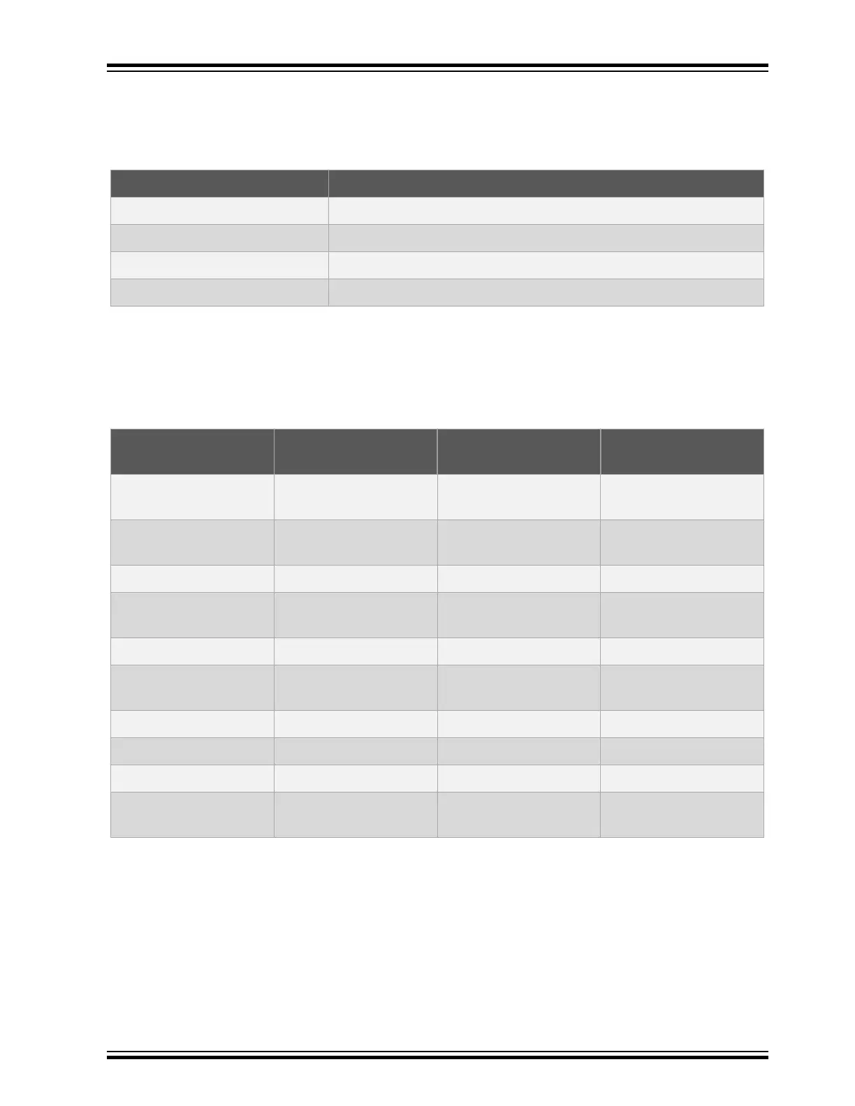
Table 5-9. USB Connections
SAM E54 pin USB function
PC00 VBUS Detection
PC19 USB ID
PA24 USB D-
PA25 USB D+
5.2.8 Cortex Debug Connector
SAM E54 Xplained Pro has a 10-pin 50-mil Cortex Debug Connector with SWD that can be used to
attach external debuggers to the ATSAME54P20A. Microchip debugging tools like the Atmel-ICE and
Power Debugger can connect directly to this connector.
Table 5-10. Cortex Debug Connector
Cortex Debug
Connector pin
Pin/Net Function Shared functionality
1 [VCC] VCC_TARGET_P3V3 ATSAME54P20A
voltage
2 [SWDIO/TMS] PA31 SW bidirectional data TRACE and EDBG
SWD
3 [GND] GND Ground
4 [SWCLK/TCK] PA30 SW clock signal TRACE and EDBG
SWD
5 [GND] GND Ground
6 [SWO/TDO] PB30 SW output TRACE and EDBG
SWD
7 [KEY] - -
8 [NC/TDI] - -
9 [GNDDetect] GND Ground
10 [nRESET] RESETN Target reset signal RST BTN, TRACE, and
EDBG SWD
5.2.9 Cortex Debug Connector with Trace
ATSAME54P20A supports 4-bit parallel trace. SAM E54 Xplained Pro implements a 20-pin, 50-mil Cortex
Debug + ETM Connector with SWD and 4-bit parallel trace. The connector is keyed (pin 7 is removed).
To use the parallel trace functionality an external debugger with trace support and 20-pin Cortex Debug +
ETM Connector pin-out has to be used. The table below shows the connections on the kit.
SAM E54 Xplained Pro
© 2017 Microchip Technology Inc.
DS70005321A-page 22