6
L It may cause electric shock or any possible harm to you if the power is not switched off.
Step 2: Prepare cable with corresponding connectors for each type of port in use.
Step 3: Connect one end of the cable to the switch and the other end to a desired device.
Step 4: Once the connections between two end-devices are made successfully, turn on the
power.
Note: If you have no modules, please skip this section.
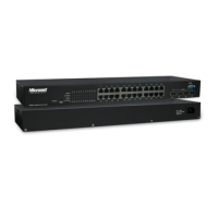
z Connecting the SFP Module to the Chassis:
The optional SFP modules are hot swappable, so you can plug or unplug it before or after
powering on.
Step 1: Verify that the SFP module is the right model and conforms to the chassis
Step 2: Slide the module along the slot. Also be sure that the module is properly seated
against the slot socket/connector
Step 3: Install the media cable for network connection
Step 4: Repeat the above steps, as needed, for each module to be installed into slot(s)
Step 5: Have the power ON after the above procedures are done
In making a switch interconnection, you could use any port to connect another switch with
straight or crossover cable. As all the ports support auto-uplink (MDI / MDI-X) function,
using a straight cable to make a switch-to-switch connection is allowed.
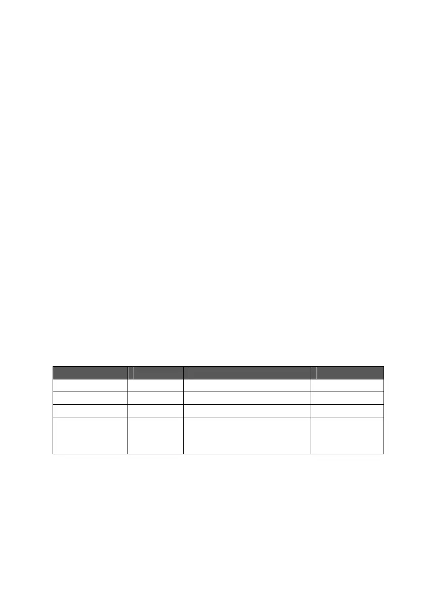
For cable selection, refer to the following table:
Network Speed Connector Cable Type Max. Length
10Mbps RJ-45 Cat. 3, 4, 5 UTP/STP 100 meters
100Mbps RJ-45 Cat. 5 UTP/STP 100 meters
1000Mbps RJ-45 Cat. 5, 5e UTP/STP 100 meters
SFP LC 62.5/125 µm multi-mode fiber
50/125 µm multi-mode fiber
9/125 µm single-mode fiber
220 meters
550 meters
10 kilometers
Note:The SFP slot shares the same LED indicator with the last 4 RJ-45 (copper) ports.