This document is strictly private and confidential, reproduction without Micropack approval is prohibited. © Micropack Engineering Ltd, 2018
3.3 Wiring Procedure
The wiring terminals are in the rear section of the detector enclosure and are accessible by
removal of the end cap.
The front section of the enclosure should only be accessed by trained personnel.
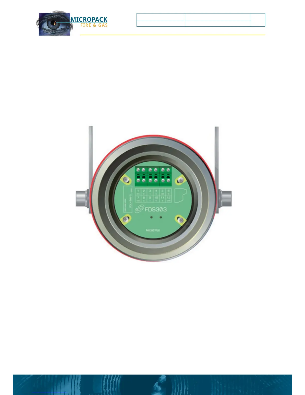
The terminal schematic detailed below shows the view looking inside the detector following
removal of the end cap.
Figure 4: Terminal Schematic
The detector has two types of alarm output available simultaneously
• 0-20mA (source non-isolated)
• Relay (Alarm & Fault)
Listed below are wiring options dependent on the functional requirements of the detector.