Chapter 4 Optics and Lighting
4-10 MicroHAWK MV-20 / MV-30 / MV-40 Smart Camera Guide
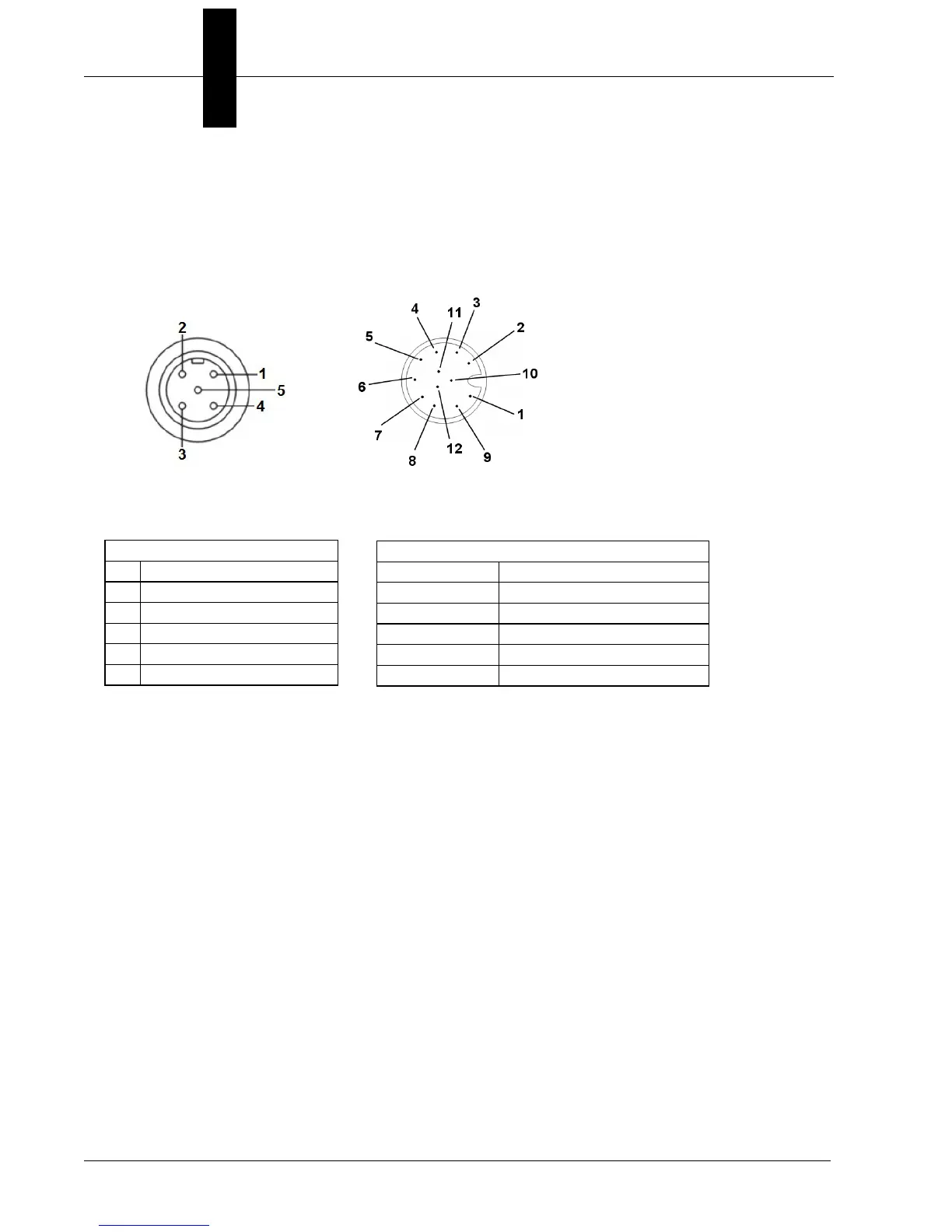
Wiring for Strobe Illumination (PNP)
Warning: Contact between Pin 5 (gray wire) and any ground or voltage source less than
or equal to 3.5VDC may cause erratic operation in this configuration. Contact between Pin
5 (gray wire) and any voltage source greater than 3.5VDC will damage the illuminator.
* Insulate Pin 5 (gray wire)
MicroHAWK MV-40
Connector A
Smart Series Illuminator
Connector
Smart Series Illuminator
Pin Signal Name
1
+24VDC
2
Trigger –
3
DC Ground
4
Trigger +
5
Dim
MicroHAWK (Connector A)
Pin Signal Name
2 and 12
Power and Output Common
7
Ground
7 Ground
6
Output 3
No Connection* N/A
 Loading...