21 M32 DIGITAL CONSOLE User Manual
6. Adjust the fourth encoder to select to which of the six mute groups the
currently selected channel will be assigned.
7. Tap the fourth encoder to assign the currently selected channel to the
selected mute group.
8. Tap the fth encoder to toggle solo on/o for the currently
selectedchannel.
9. Turn the sixth encoder to adjust the fader level for the currently
selectedchannel.
10. Tap the sixth encoder to toggle mute on/o for the currently
selectedchannel.
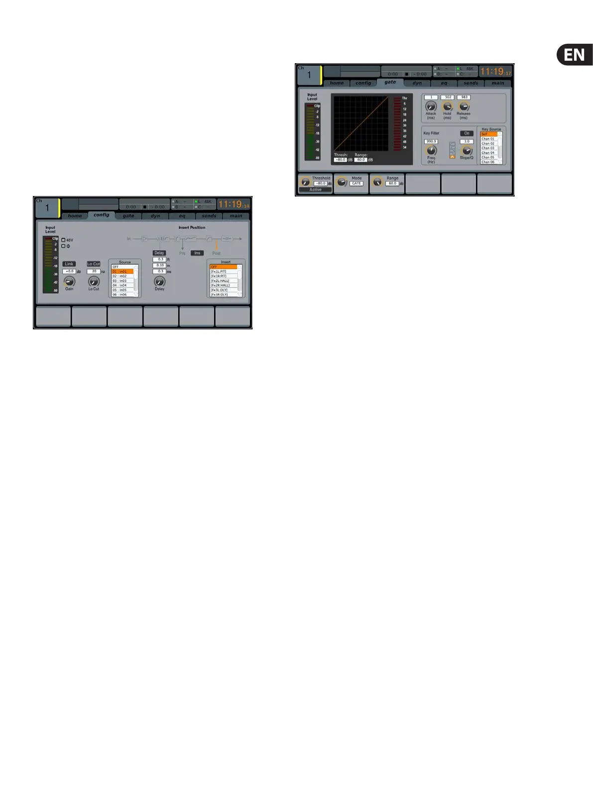
cong
The conguration tab allows selection of signal source/destination for the
channel, conguration of insert point, and other settings, as well as conguration
of the channel delay.
The cong tab of input channels 1-32 contains the following parameters
that can be adjusted using the six push encoders:
1. Turn the rst push encoder to adjust the input gain (trim) of
thechannel.
2. Tap the rst encoder to allow linking of the channel to the
adjacentchannel.
3. Adjust the second encoder to set the low-cut frequency of the channel.
4. Tap the second encoder to toggle the low-cut lter in/out of the
signalpath.
5. Adjust the third encoder to scroll among all of the possible sources for
the channel.
6. Tap the third encoder to select the currently highlighted source and
assign it to the channel.
7. Adjust the fourth encoder to set the amount of digital line delay applied
to the channel.
8. Tap the fourth encoder to toggle the delay in/out of the signal path.
9. Adjust the fth encoder to toggle the channel insert between pre- and
post-EQ/compressor.
10. Tap the fth encoder to toggle the channel insert in/out of the
signalpath.
11. Adjust the sixth encoder to scroll among the signal path choices for the
insert point.
12. Tap the sixth encoder to assign the selected signal path to the
insertpoint.
NOTE: Mix Bus channels do not have Gain, Low Cut, Phantom, Phase, Source
and Delay. But they do have a macro feature for setting all channel send taps to
the selected bus at once. As an example, this can be used for switching all sends
from Pre Fader to Post Fader or for ensuring that all channel taps are consistent.
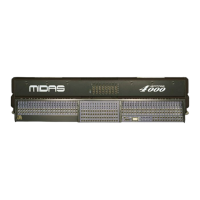
gate
The gate tab displays all aspects of the channel noise gate, and allows for very
deep control of the gate eect. Whereas the top panel’s dedicated GATE section
allows control of the gate’s threshold and in/out status, the gate tab oers many
more controls. This tab can be accessed directly by pressing the VIEW button in
the top panel GATE section.
The gate tab contains the following parameters, divided among two pages,
that can be adjusted using the six push encoders:
Page 1
1. Adjust the rst push encoder to set the input threshold of the gate.
2. Tap the rst encoder to toggle the noise gate in/out of the signal path.
3. Adjust the second encoder to set the range of a ‘ducking eect applied
to the channel.
4. Tap the second encoder to toggle the ducker eect in/out of the
signalpath.
5. Adjust the third encoder to set the attack time of the onset of the noise
gate eect.
6. Adjust the fourth encoder to set the hold time of the noise gate eect.
7. Adjust the fth encoder to set the release time of the noise gate,
controlling how quickly the gate opens up and lets the signal through.
Page 2
1. Push encoders 1 & 2 function the same on pages 1 & 2.
2. Adjust the fourth encoder to set the frequency of the key lter that can
be used to trigger the noise gate.
3. Tap the fourth encoder to toggle the key lter on/o, allowing a specic
frequency to control the gate.
4. Adjust the fth encoder to set the steepness of the EQ slope used in the
key lter.
5. Tap the fth encoder to send the key source to the solo bus, allowing
the key source to be monitored and evaluated.
6. Adjust the sixth encoder to select the specic key source to be used.
Choices include ‘Self’ (the channel’s own signal), as well as any other
input/output of the console.
7. Tap the sixth encoder to assign the selected key source to the gate.