22 M32 DIGITAL CONSOLE User Manual
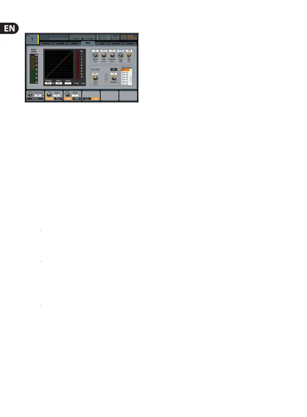
dyn
The dynamics tab displays all aspects of the channel compressor, and allows for
very deep control of the eect. Whereas the top panel’s dedicated compressor
section allows control of the threshold and in/out status, the dyn tab oers many
more controls. This tab can be accessed directly by pressing the VIEW button in
the top panel DYNAMICS section.
The dyn tab contains the following parameters that can be adjusted using
the six push encoders:
Page 1
1. Adjust the rst push encoder to set the input threshold of
thecompressor.
2. Tap the rst encoder to toggle the compressor in/out of the signal path.
3. Adjust the second encoder to set the ratio of the compressor.
4. Tap the second control to switch the channel dynamics eect between
compression and expansion.
5. Adjust the third encoder to set the attack time of the compressor eect.
6. Tap the third encoder to switch the compressor between Peak and RMS
(root mean squared) mode, where the average level of the signal is
evaluated more than any specic peak of the channel material.
• PEAK: A peak-sensing compressor responds to the instantaneous
level of the peak signal. While providing tighter peak control,
peak sensing might yield very quick changes in gain reduction,
moreevident compression, or sometimes even distortion.
Thismode is suitable for control/limiting of dynamic material.
• RMS: In this mode, the compressor applies an average function
on the input signal before its level is compared to the threshold.
Thisallows a more relaxed compression that also more closely
relates to our perception of loudness. Sharp dynamic transients
will be less aected in this mode. This mode is good for controlling
levels in amix.
7. Turn the fourth encoder to adjust the hold time of the compressor.
• Hold time is a parameter not often found on commercial units, but
is very useful. If a compressor is set to use a very fast attack/release
time, audible distortion can occur, because the compressor is trying
to work on individual waveform cycles of the signal instead of the
sound envelope as a whole. The Hold parameter works around this
issue by providing a short delay. This delay prevents the compressor
from releasing until a certain period of time has elapsed.
8. Tap the fourth encoder to switch between Linear and Logarithmic
modes for the compressor. Following are some brief descriptions of
those dierent modes:
LOG: This mode is used in many well-respected compressors and is the
natural result of more recent analogue units employing logarithmic
side chains and resistor/capacitor time constants. The exponential/
dB law has some interesting characteristics. Firstly the time taken to
complete a compression event tends to stay the same however large
the dynamic signal excursion is. Also, since the peak rate of gain change
increases with dynamic excursion, the resulting harmonic content due
to compress tends to follow the loudness of the signal in a way that
the ear expects. This helps to mask the eect of the compressor and
thus provides the most forgiving solution, being tolerant of diering
timing settings and signal material. This makes it the best choice
for general compression use and overall dynamic control of complex
musicalsignals.
LINEAR: In this mode, the rate if gain change is constant (as set by the
timing controls). Therefore the greater the signal dynamic excursion,
the longer the compressor will take to complete a gain change.
Also,since the total time that the compressor spends in attack or decay
is proportional to the size of the gain excursion, the harmonic content
of the compression artefact will seem to reduce in frequency content,
the louder the signal excursion. This type of compressor is useful for
generating dynamic sound eects because the sonic character of the
compressor is much more aected by time control settings and signal
material than the exponential type.
9. Adjust the fth encoder to set the release time of the compressor.
10. Adjust the sixth encoder to set the makeup gain of the compressor;
useful when the compression eect has reduced the overall signal level
of the channel too much.
Page 2
1. Push encoders 1 & 2 function the same on pages 1 & 2.
2. Adjust the third encoder to set the steepness of the compressor knee
angle between ve separate settings. Adjust this control to switch
between a harder sounding, or more transparent compressor eect.
3. Tap the third encoder to move the compressor eect before or after the
EQ in the channel signal path.
4. Adjust the fourth encoder to set the frequency of the key lter that can
be used to trigger the compressor.
5. Tap the fourth encoder to toggle the key lter on/o, allowing a specic
frequency to control the compressor.
6. Adjust the fth encoder to set the steepness of the EQ slope used in
thecompressor.
7. Tap the fth encoder to send the key source to the solo bus, allowing
the key source to be monitored and evaluated.
8. Adjust the sixth encoder to select the specic key source to be used,
Choices include ‘Self’ (the channel’s own signal), as well as any other
input/output of the console.
9. Tap the sixth encoder to assign the selected key source to
thecompressor.