Mid-Continent Instruments and Avionics, Wichita, KS
REV. B, October 31, 2012 15 Manual Number 9017782
2.5 CABLE HARNESS
Construct the cable harness with regards to the instructions below and using the Connector Pinout of
Table2.1 and Figure 2.2 and Configuration Module Assembly of Figure 2.3. Installers should follow
industry-accepted practices regarding aircraft wiring and applicable regulatory and advisory requirements
and guidance.
Refer to Section 2.3: Equipment Location in regards to routing precautions.
2.5.1 WIRE GAUGE SELECTION
Wire gauge should be 22 AWG. Use of PTFE, ETFE, TFE, Teflon, or tefzel insulated wire
is recommended for aircraft use per MIL-DTL-16878 or equivalent for the connections as
noted below. Additionally, for data signals associated with ARINC 429 inputs and outputs,
shielded twisted pair wiring per M27500 or equivalent is recommended (pin pairs 3/8 and
12/13).
2.5.2 CONFIGURATION MODULE
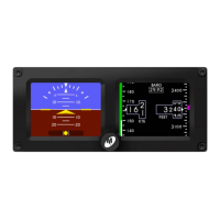
The supplied custom configuration module is required for proper installation and
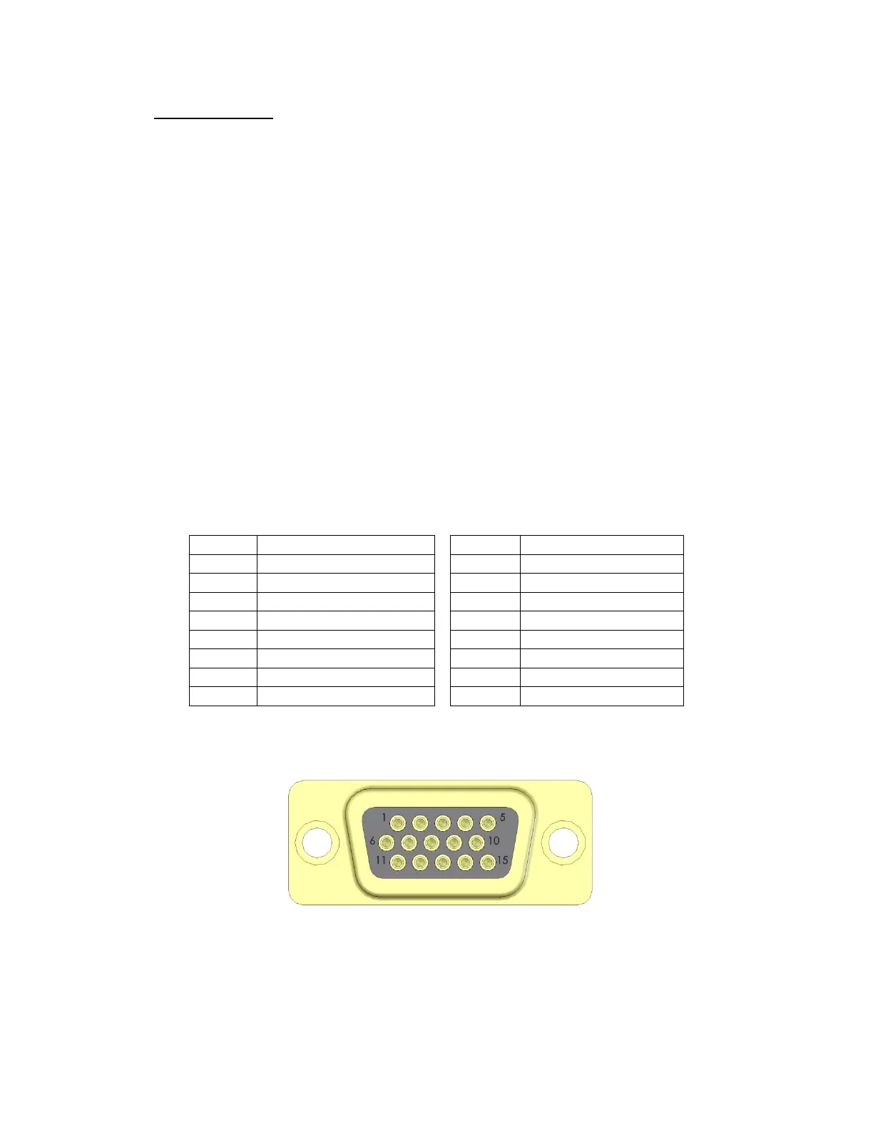
operation of the MD302 unit. The functions associated with the 15-pin D-subminiature
connector are identified as follows:
15-pin D-Sub Connector
Pin No. Description Pin No. Description
1 +10-32VDC Input 8 ARINC Out A
2 Valid Signal Out 9 Reserved
3 ARINC Out B 10 Config Module Clock
4 Reserved 11 Reserved
5 Config Module Power 12 ARINC In A
6 Power Return / Ground 13 ARINC In B
7 Lighting Bus Input 14 Config Module Data
15 Config Module Return
TABLE 2.1
FIGURE 2.2
VIEW FROM REAR OF MATING CONNECTOR
 Loading...