Mid-Continent Instruments and Avionics, Wichita, KS
REV. B, October 31, 2012 40 Manual Number 9017782
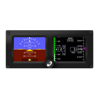
FIGURE 4.13
MMO ENTRY PAGE AND SAMPLE SCREEN
4.4.3 RANGE MARKINGS
The RANGE MARKINGS setting allows the installer to input airspeed limits (or “V-speeds”)
specific to the aircraft. Aircraft airspeed limits can typically be found in the Pilot’s
Operating Handbook (POH). The range markings for airspeed limits appear as a series of
colored bars to the left of the airspeed tape.
To program range markings: (See Figure 4.14)
1) Use the control knob to select the width of the color bar (H = Half, F = Full)
and the desired color.
2) Press the control knob to accept the selection and move to the range values.
3) Turn the control knob to select each digit and press to move to the next
digit.
a. The first three digits are the start or lower limit of the color bar
range and the second three digits are the upper limit.
b. A ‘radial’ or tick-mark can be made at any value by selecting the Full
(F) width and desired color, then setting the lower limit and upper
limit to the same desired value.
c. The values automatically represent the units (knots, mph, kph)
selected in the CONFIGURE DISPLAY > AIRSPEED UNITS menu.
4) Continue in sequence until reaching the EXIT prompt and press the control
knob to exit the menu.
a. Leaving or selecting “000” for the lower and upper limit creates no
color bar.
Note: Per AC 23.1311-1C, V
NE
or V
MO
aircraft should use Full Red color bars between 0
and V
SO
and between V
NE
/V
MO
and the tape limit (500 knots or equivalent).
FIGURE 4.14
 Loading...