M thermal Mono
202005 13
Part 1 - General Information
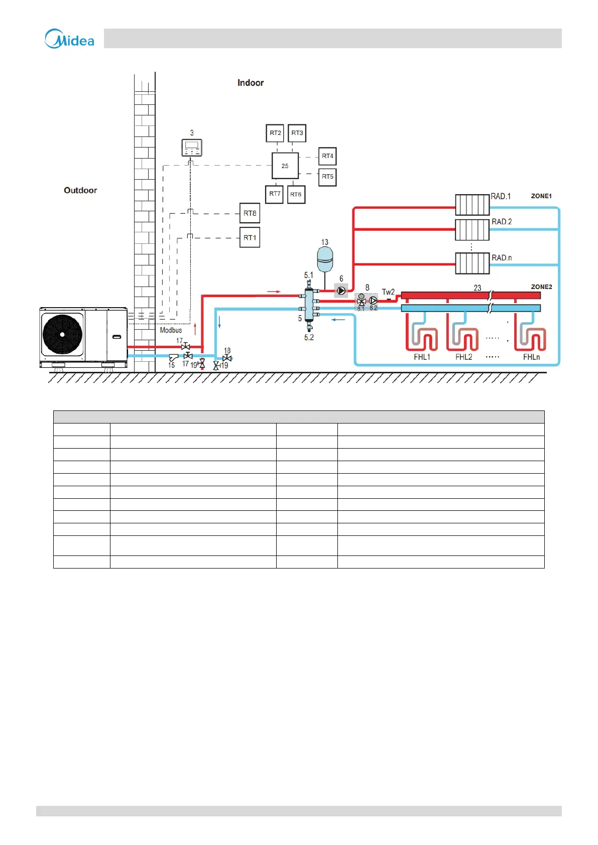
5.2.3 Double zone control
Figure 1-5.4: Application 2-Double zone control
Shut-off valve (Field supply)
Shut-off valve (Field supply)
Balance tank (Field supply)
Filling valve (Field supply)
Drainage valve (Field supply)
Collector/distributor (Field supply)
P_o: Zone A circulation pump (Field supply)
Hydraulic adapter box (Optional)
Mixing station (Field supply)
Low voltage room thermostat (Field supply)
SV3: Mixing valve (Field supply)
High voltage room thermostat (Field supply )
Floor heating loop (Field supply)
Expansion vessel (Field supply)
Zone 2 water flow temperature sensor
(Optional)
Notes:
1. The example is just for application illustration; please confirm the exact installation method according to the installation manual.
Space heating
Zone1 can operate in cooling mode or heating mode, while zone2 can only operate in heating mode; While
installation, for all thermostats in zone1, only “H、L” terminals need to be connected. For all thermostats in zone2,
only “C、L” terminals need to be connected.
1) The ON/OFF of zone1 is controlled by the room thermostats in zone1. When any “HL” of all thermostats
in zone1 closes, zone1 turns ON. When all “HL” turn OFF, zone1 turns OFF; Target temperature and
operation mode are set on the user interface;
2) In heating mode, the ON/OFF of zone2 is controlled by the room thermostats in zone2. When any ”CL” of
all thermostats in zone2 closes, zone2 turns ON. When all “CL” open, zone2 turns OFF. Target
temperature is set on the user interface; Zone 2 can only operate in heating mode. When cooling mode
is set on the user interface, zone2 keeps in OFF status.
 Loading...
