M thermal Mono
82 202005
Midea M thermal Mono Engineering Data Book
5 DIP Switch Settings
DIP switches S1 and S2 on the hydronic system main PCB should be used to specify refrigerant piping length and to specify
whether certain components have or have not been installed. Refer to Table 3-5.1 and to the M thermal Mono Service
Manual, Part 4, 2.2 "Main PCB for Hydronic System".
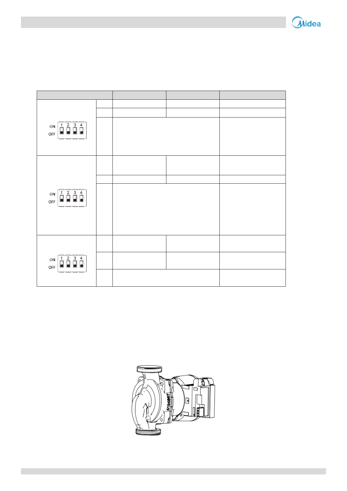
Table 3-5.1: DIP switch settings
00=Without IBH and AHS
10=With IBH
01=With AHS for heating mode
11=With AHS for heating mode
heating and DHW
Start pumpo after
six hours will
be invalid
Start pumpo after
six hours will
be valid
00=variable speed pump
(Max head:8.5m,Grundfos)
01=constant speed pump
(WILO)
10= variable speed pump
(Max head:10.5m,Grundfos)
11=variable speed pump
(Max head:9.0m, WILO)
6 Internal Circulation Pump
The pump is controlled via a digital low-voltage pulse-width modulation signal which means that the speed of rotation
depends on the input signal. The speed changes as a function of the input profile. The relationship between external static
pressure and water flow rate is described in Part 2, 7 “Hydronic Performance”.
Figure 3-6.1: Internal circulation pump
 Loading...
