Service manual, 2016-12
31 / 42
10.Circuit description
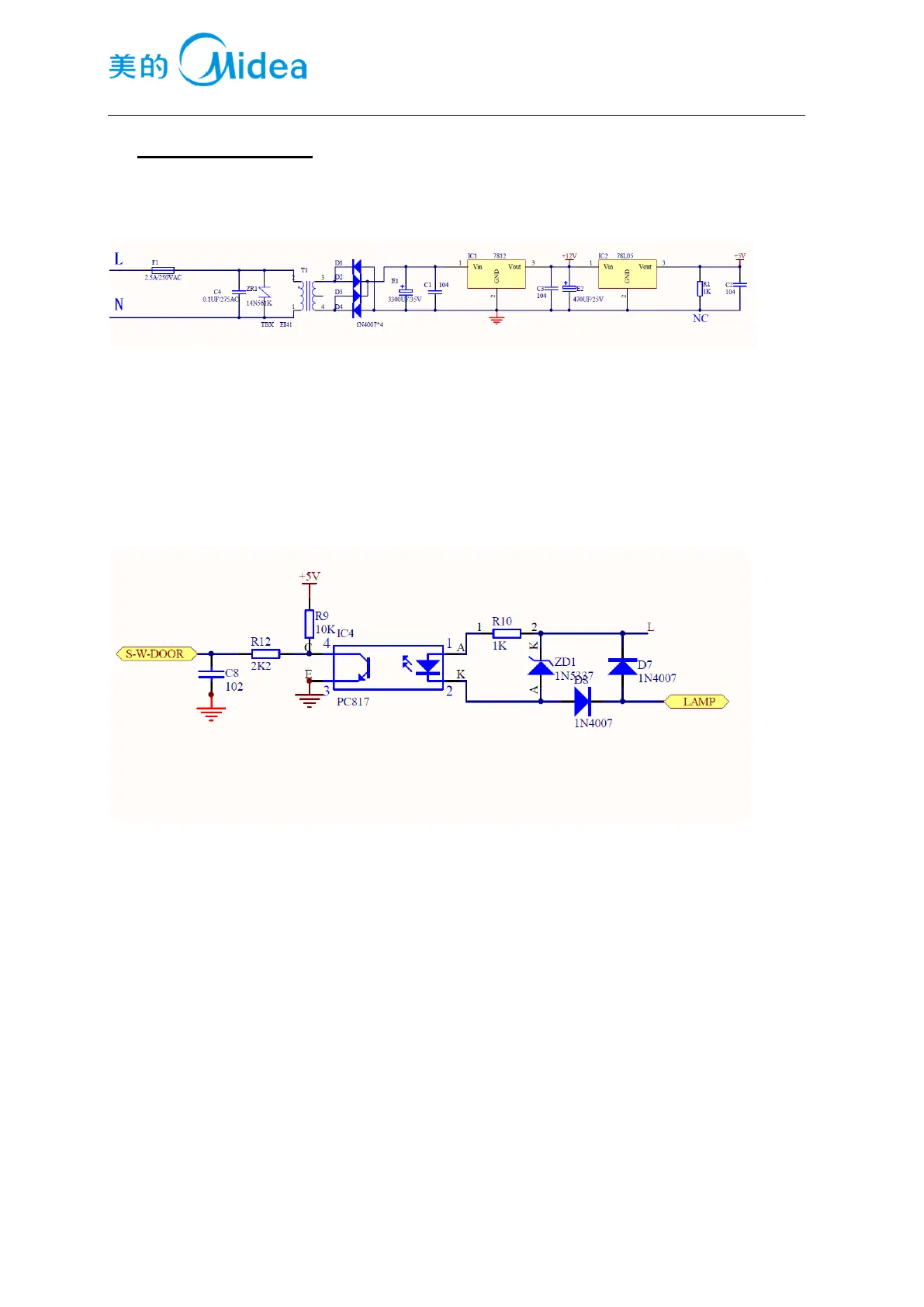
10.1 Power Supply
AC input power will be treated by transformer ,and rectified when through D1~D4,then filtered by E1
capacitor .it will output stable DC12V after through there terminal regulator 7812, DC12V is for provide
power to relay(control strong electricity), the relay is for control the on-off of compressor, and the
defrosting heater. DC12V will be changed into DV5V after through modifier 7805, 5V is for provide
power to main PCB , main PCB monitors the status of inside temperature.
10.2Door trip test circuit
Current of strong electricity of lamp will be output onto terminal of weak currnet side by PC817
opto-isolator, then reduced voltage by R10,and rectified by D7 and D8. When door is opened , the circuit
of switch is closed, and the PWM wave is detected by the terminal of weak current, and main PCB
receive the signal. When door is closed, the circuit of switch is open, no wave is detected, and main
PCB judge it as the signal of door closed
10.3Temperature test circuit
It’s conducted by the sensor, making use of the characteristics that resistance value reduces as the
temperature increases, and the thermistor that has temperature coefficient of resistance in medium
temperature.