33
www.midlandradio.com
Version 5.1
680-090-2042
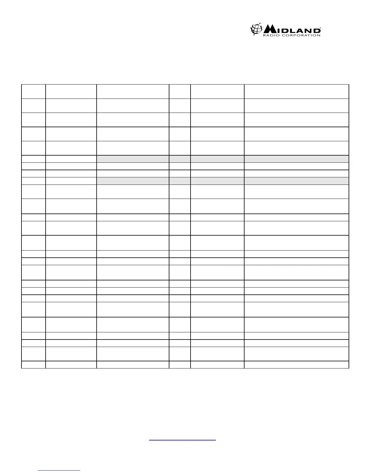
36. Option Port Pinout
25 pin D-sub connector for remote control is provided on the rear panel of Base
Tech III. The functions of each pin are as follows:
Pin
No.
Name Description I/O Levels Comments
1 CH0 LSB external binary
channel selection
I 0-+3.3VDC 0000 is channel 1
2 CH1 External binary channel
selection
I 0-+3.3VDC
3 CH2 External binary channel
selection
I 0-+3.3VDC
4 CH3 MSB External binary
channel selection
I 0-+3.3VDC 1111 is channel 16
5 Unassigned
6 REM MON Remote Monitor I 0-+3.3VDC +3.3V=Monitor On
7 GND Ground
8 Unassigned
9 REM D/A Remote Digital Analog
select
0V – 3.3V +3.3V = Analog
0V = Digital
10 DEM OUT Discriminator audio out O
≈330mVrms
1KHz @ ±3KHz
C4FM on DIGITAL MODE
11 BUSY Channel busy indication O 0-+3.3VDC +3.3V=busy
12 RSSI Receive signal strength
indicator
O 0-+2.5VDC
analog
13 MOD1 External audio
modulation input
I
≈50mVrms 1Khz
for ±3KHz
14 GND Ground
15 PTT Push to talk I 0-+3.3VDC 0V=transmit
16 MOD2 External modulation
input
I
≈400mVrms
1KHz for ±3KHz
After limiter and filtering /LOW FREQ
i.e. External CTCSS/DCS IN
17 SIMP Simplex mode selected O 0-+3.3VDC 0V=simplex
18 ERR Alarm indication O 0-+3.3VDC Duty Cycle Determines which alarm
19 DECODE Decode valid indication O 0-+3.3VDC 5V=valid signaling
20 RX AUD1 Buffered receive audio O
≈700mVrms
1KHz @ ±3KHz
1 & 2 Can produce 0 dBm into
21 RX AUD2 Buffered receive audio O
≈700mVrms
1KHz @ ±3KHz
600 ohm input
22 TX OUT O
23 EXT PW/SW External power switch I 0-Open source 0V=ONf
24 REMOTE External channel
selection mode
I 0-+3.3VDC 0V=external
25 +12V O 12 vdc 800mA Max out
NOTE: Pins 1-4, 6 and 9 are only available when pin 24 (Remote Mode)
is at 0V. See page 23 for more information on display indications