26
www.midlandradio.com
Version 5.1
680-090-2042
26. ADJUSTMENT MODES
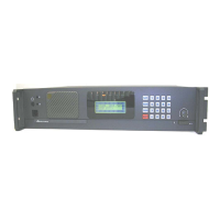
While Grounding TP-2 on the analog logic board, switch the radio on.
(See the Midland Base Tech III Service Manual for the TP-2 location)
Press # to change selections.
Press A (Up) and B (Down) to adjust the level.
-RX 0 dBm Out =Rx 0 dBm output level adjustment (At pins 20 & 21 on the
EXT OPTION 25 pin D-sub connector).
-RX FX828 MOD-1 =Deviation level adjustment for “Repeat” mode (analog)
-TX DIGITAL DEV =Deviation level adjustment (digital)
- TX ANALOG DEVI =Deviation level adjustment (analog)
-TX TONE DEVI =CWID Deviation level adjustment
(The CWID level must be adjusted before it will send any code)
You must reboot the radio to return to normal operation
Figure-48 Displays RX wide 0dbm out
Figure-49 Displays RX MOD-1, Modulation adjustment for repeat mode
Figure-50 displays TX MOD-Digital
Figure-51 displays TX MOD-Analog (TXW for Wide and TXN for narrow) whatever
the current channel is programmed for.
Figure-52 displays TX TONE DEVI, This is the CWID level adjustment.