4
www.midlandradio.com
Version 5.1
680-090-2042
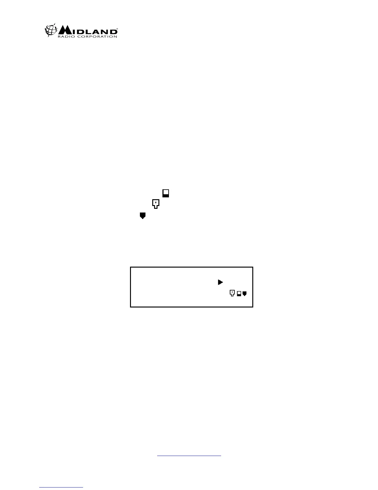
1. LCD DISPLAY
1.1 LCD display consists of 4 x 20 characters as shown.
Line 1: The Incoming RSSI with 10 steps
Line 2: The output power levels with 10 steps
Line 3: The left 4 letters show channel numbers. The middle 8 letters
shows the channel name (if not programmed, it will be blank).
The right 4 letters displays the status of the radio as described below.
a. RX mode: M= Mix, both analog and digital can be received
D= Only digital can be received.
b. TX mode: D=PTT digital transmission A=PTT analog transmission
c. Monitor mode: ⌧= Monitor off
S= Selective squelch
d. P-25 squelch: N= Normal squelch
S= Selective squelch
e. Low Voltage Icon: = Low Voltage state (Icon flashes with ALM LED)
f. Key lock mode: =Key lock (Not displayed if in Low Voltage alarm)
g. Shift mode: SHIFT KEY ICON (reverts to normal within 2 seconds)
Line 4: The left 2 letters show GPC (GROUP CALL), AC (ALL CALL),
IC (INDIVIDUAL CALL).
The right 18 letters displays the GROUP NAME, INDIVIDUAL
NUMBERS, ETC.
RX = = = = = = = = = =
TX = = = = = = = = = =
C001 TAC 2 MD⌧N
GPC 500
2. LED DISPLAY
The Midland Base Tech III has 5 LED's
From left to right;
DIGI= The LED is on when receiving a digital signal
REP= The LED is on when in repeat mode.
(The BASE TECH III can be programmed for,
SIMPLEX -SEMIDUPLEX - DUPLEX- REPEATER on a per channel basis.)
ALM= The LED flashes when an error on either TX or RX occurs
TX= The LED is on when in Transmit
BUSY= The LED is on when receiving a signal.