11
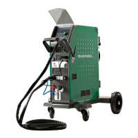
Connection and operation
Warning
Read warning notice and
instruction manual carefully
prior to initial operation and
save the information for
later use.
Permissible installation
Mains connection
Connect the machine to the correct mains supply.
Please read the type plate (U
1
) on the rear side of the
machine.
0
l
1
2
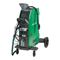
Connection of shielding gas/plasma gas
Connect the gas hoses, which branch off from the back
panel of the welding machine (3), to a gas supply with
pressure regulator (2-6 bar) for shielding gas. (Note:
Some types of pressure regulators require an output
pressure of more than 2 bar to function optimally).
Connect the gas hose for plasma gas to 1-5 bar.
Important!
In order to avoid destruction
of plugs and cables, good
electric contact is required when
connecting earth cables and
welding hoses to the machine.
1. Mains connection
2. Power switch
3. Gas hose
4. Connection of shielding gas
5. Connection of plasma gas
6. Connection of TIG/PLASMA Welding hose
7. Connection of earth clamp (TIG/PLASMA) or electrode holder
8. Connection pilot arc (PLASMA)
9. Connection 7-pole plug (TIG)
10. Connection of cooling hoses - internal cooling TIG 500A/PLASMA 80A
11. Connection of cooling hoses - internal cooling TIG 500A/PLASMA 80A
12. Cooling liquid level control
13. Refill of cooling liquid
14. Connection of remote control
15. Connection of cooling hoses -
external cooling TIG 500A/PLASMA 350A
16. Connection of cooling hoses -
external cooling TIG 500A/PLASMA 350A
17. CAN connection
Gas 2-6 bar
Power
1
F
F
F
3
Plasma
gas
1-5 bar
3
15
16
2
14
5
8
4
6
7
9
10
11
12
13
15
16
17
Cooling Unit
rød/red/rot/rouge
 Loading...