9 MM660 Installation Instructions
Technical Specifications
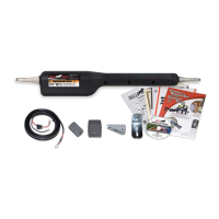
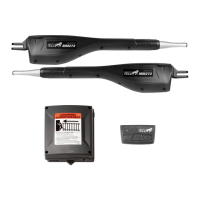
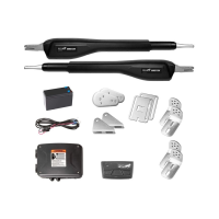
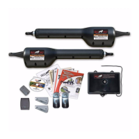
Mighty Mule 660 Gate Opener
Gate Weight
Gate Length
Number of Cycles* Per Day
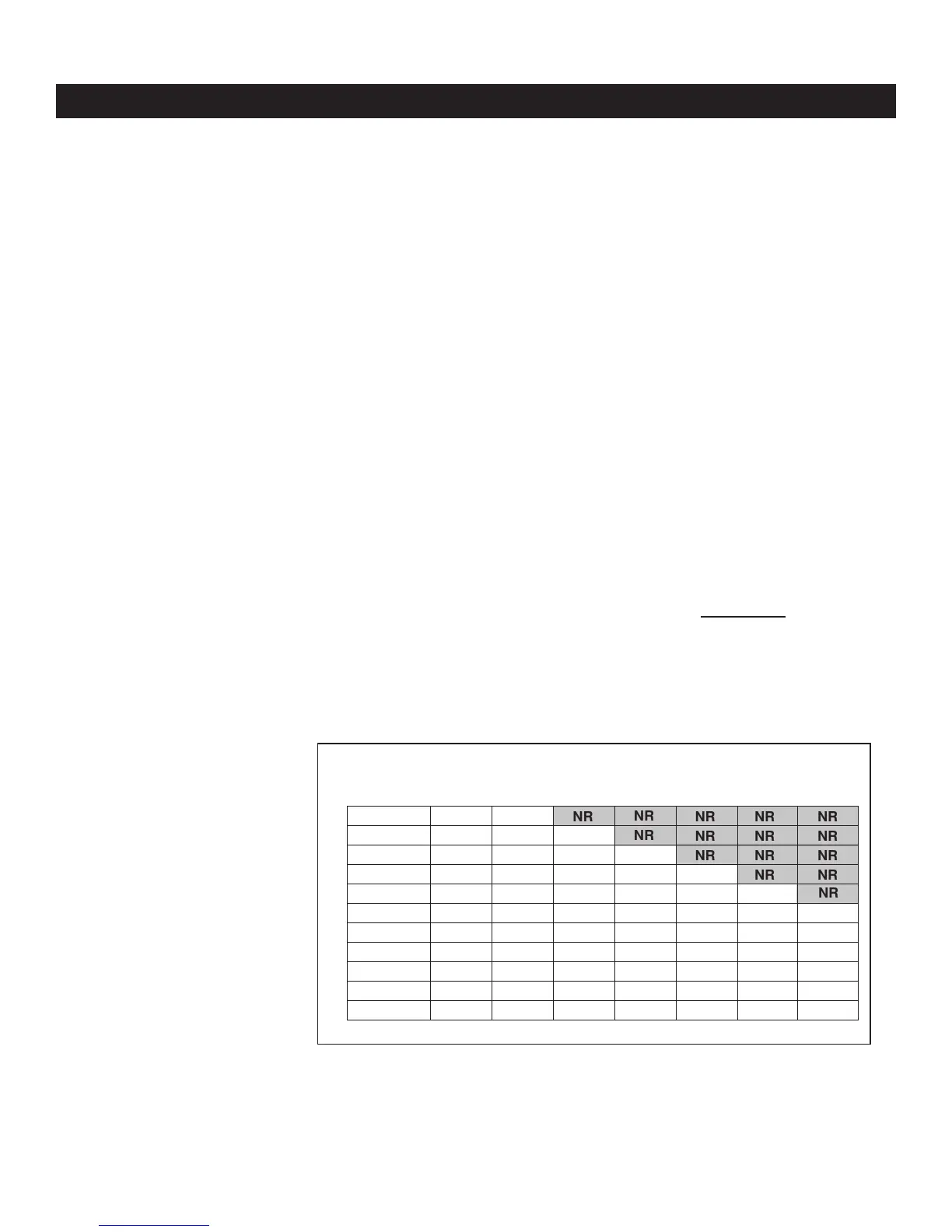
Mighty Mule 660 Gate Capacity /Cycle Chart
Estimated number of daily cycles, based on use with a transformer and one(1) 12 Volt battery.
850 lbs.
750 lbs.
650 lbs.
550 lbs.
450 lbs.
350 lbs.
250 lbs.
150 lbs.
100 lbs.
50 lbs.
135
145
155
165
175
185
195
205
215
225
5’ - 6’
125
135
145
155
165
175
185
195
205
215
8’
125
135
145
155
165
175
185
195
205
10’
125
135
145
155
165
175
185
195
12’
125
135
145
155
165
175
185
14’
125
135
145
155
165
175
16’
NR
NR
NR
NR
NR
125
135
145
155
165
18’
NR
NR
NR
NR
NR
NR
NR
NR
NR
NR
NOTE: “NR” indicates this size
and weight combination is not
recommended for the
Mighty Mule 660.
NOTE: Ball bearing hinges
should be used on all gates
weighing over 250 lb.
To determine the number of cycles the gate operator will perform using solar panels (see page 23).
* An operation cycle is one full opening and closing of the gate.
These specications are subject to change without notice.
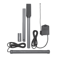
DRIVE
• Low friction screw drive (linear actuator) rated for -5 ºF to
+160 ºF (-20 ºC to +71 ºC). Use of heater bands on arm and
control box will enhance performance in extreme cold tempera-
tures.
• Powered by a 12 V motor with integral case hardened steel
gear reducer. Motor speed reduced to 260 rpm. Generates 680
ft. lb. of torque at 12 V.
• Maximum opening arc of 110º. Approximate opening time
(90º): 20 seconds, depending on weight of gate.
POWER
• The system is powered by a 12 Vdc, 7.0 Ah, sealed,
rechargeable acid battery.
• Battery charge is maintained by a 120 Vac, 18 Vac output trans-
former. One lade-style control board fuse is rated for 15 A.
NOTE: The transformer should not be directly connected
to any battery. Do not replace fuses with higher ampere
rated fuses; doing so will void your warranty and may
damage your control board.
• OPTIONAL: Battery charge is maintained by GTO Solar Panel
Charger Kit (5 Watt minimum).
CONTROL
• The Mighty Mule microprocessor-based control board is set for
single leaf, pull-to-open gate installations. DIP switches can be
adjusted to accommodate an optional kit for push-to-open gates
(see Accessory Catalog).
• A circuit on the control board regulates charging. “Sleep draw”
is 25 mA; “active draw” is 2 to 5 A.
• Auto-memorization of digital transmitter code.
• GTO remote-mounted RF receiver tuned to 318 MHz.
• Operator length with push-pull tube fully retracted is
40-1/4” mounting point to mounting point. Max stroke 20”.
• Adjustable auto-close timer (3 to 120 s), and Dual Sense Tech-
nology Stall Force.
• Power terminal block accommodates a transformer or solar
panels. NOTE: Do not use solar panel and transformer at
the same time.
• DIP switches simplify setup of gate operator.
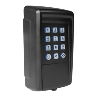
• Accessory terminal block fully compatible with push
button controls, digital keypads, loops, etc.
• Control board allows connection of edge sensors and photo-
electric sensors.
• Audio entrapment alarm sounds if unit encounters an
obstruction twice while opening or closing.
OPERATIONAL CAPACITY
• The Gate Capacity Chart shows approximate cycles, per day,
you could achieve prior to the battery depleting to a state where
the unit will not function. This chart reects a Mighty Mule
Automatic Gate Opener when charging with a transformer.
Actual cycles may vary slightly depending upon the type and
condition of gate and installation.