31 MM660 Installation Instructions
Connecting Additional Devices
NOTE:
• All control inputs are dry-contact, normally open, inputs. DO NOT apply external voltage sources to these inputs.
• All inputs are connected with respect to COMMON terminal.
• The status light will blink once when its corresponding input is activated.
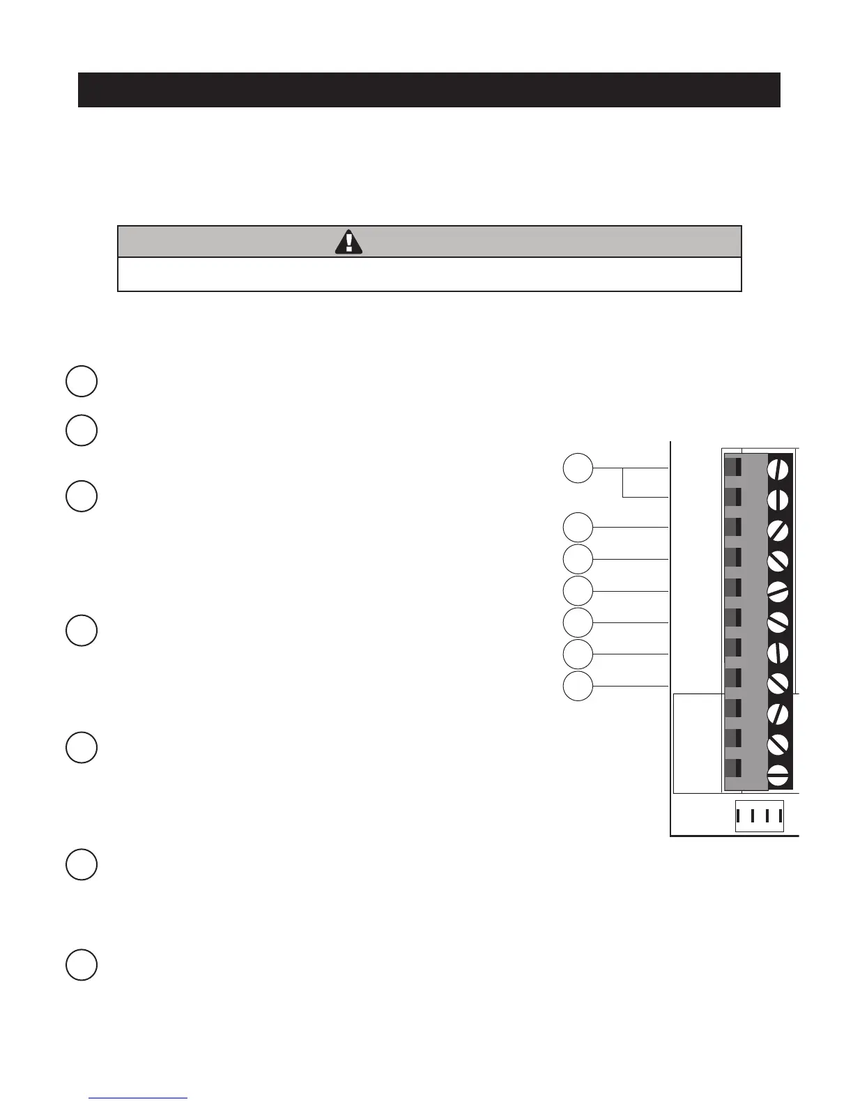
Input Connections
Mighty Mule strongly recommends the use of additional obstruction detection devices however we do not endorse any spe-
cic brand names. Only use products that are listed to be in compliance with any applicable UL safety standards and national
and regional codes.
PLEASE NOTE: Contact sensors, non-contact sensors, shadow loops, etc. are not included with the Mighty Mule. Refer to
the sensor manufacturer’s instructions for information about installing accessory devices.
The Mighty Mule ONLY accepts accessory devices with normally open dry contact outputs.
1 COM: Circuit common (reference for all logic input)
• Two (2) terminals to provide extra common connection point.
2 CYCLE: (Typically for use with doorbell button or hardwired key pad)
• Each activation at this input will cycle the operation as follows:
….→ OPEN → STOP → CLOSE → STOP → OPEN → …
3 SAFETY: (Typically for use with photo beam device, loop detector
or other non-contact sensors)
• Activation of this input while the gate is closing will cause the gate to
stop and return to the opened position.
• Activation of this input while the gate is opening has no effect (gate
will continue to open).
• Activation of this input while gate is idle will prevent gate from closing.
4 EXIT: (Typically for use with exit loop or wand)
• Activation of this input will open the gate if it’s not already at the
open position
• Activation of this input while at open limit will restart the auto close time
(if enabled).
NOTE: if the contact (activation) is maintained it will hold the gate in the fully open position.
5 SHADOW: (Typically for use with loop detector device)
• This input is only monitored when the gate is at the fully open
position. At any other position, activation of this input has no effect on
gate operation.
• Activation of this input while gate at the fully open position will
prevent gate from closing.
6 CLOSE EDGE: (Typically for use with safety edge device)
• Activation of this input while the gate is closing will cause the gate to
stop and reverse direction for approximately 2 seconds.
• Activation of this input while the gate is opening has no effect (gate will continue to open).
• Activation of this input while gate is idle will prevent gate from closing.
7 OPEN EDGE: (Typically for use with safety edge device)
• Activation of this input while the gate is opening will cause the gate to
stop and reverse direction for approximately 2 seconds.
• Activation of this input while the gate is closing has no effect (gate
will continue to close).
• Activation of this input while gate is idle will prevent gate from opening.
1
2
3
4
7
5
6
BAT T -
1 2 3 4
ON
RECEIVER
LEARN
MAST LIMIT
LEARN
SLV LIMIT
S3
S4
ALM
S2
OFF
SOFT START OFF
WARNING OFF
OPEN PULL
SLV OPEN DLY.
MODE1 OFF
MODE2 OFF
ON
ON
PUSH
SIMULT.
ON
ON
120 MIN MAX
CHARGING
PWR IN
GTO RCVR.
WHT
BLU
BRN
ORG
RED
BLK
GRN
WHT
BLU
BRN
ORG
RED
BLK
GRN
COM
GRN
BLK
RED
CYCLE
SAFETY
EXIT
SHADOW
OPEN
EDGE
COM
LOCK
PWR
AUX
R LY
POWER
INPUTS
CONTROL
INPUTS
MASTER CABLESLAVE CABLE
CONTROL INPUTS
CLOSE
EDGE
Make sure the operator power switch is turned OFF before connecting ANY device wiring to the terminals
of the controller. Unplugging the transformer does not turn power to the operator off.
WARNING