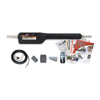
MM660 Installation Instructions 16
2" minimum
pinch-point clearance
2
1
Maximum Stroke 20”
5
Top View
Closed
Position
Open
Position
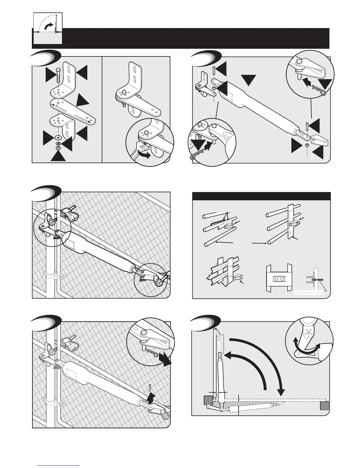
Assemble post bracket parts. NOTE: A Push-to-Open Bracket
FM148 is required for this type of installation (not included).
I
I
R
V
S
Y
PTO
Bracket
FM148
11”
1
X
X
F
M
M
Q
B
Q
2
3
Mounting Push-to-Open Opener to Gate
Attach opener to gate bracket and secure with hardware re-
quired.
With gate in CLOSED position, using clamps, secure opener to
gate post and center cross member of gate.
Gate Opener Installation
Your Property
Recommended reinforcement and gate bracket mounting
examples.
Steel Pipe Cut in Half
(not supplied)
Gate
Bracket
Thin Walled
Tube Gate
Gate
Bracket
1” x 6” Wood Reinforcement
Panel
Gate
Gate
Bracket
Wood or Metal
Reinforcement
(not supplied)
Mounting Plate
Created for
Decorative Gate
(required but not
supplied)
Remove excess bolt length
with hacksaw or bolt cutters
FRONT VIEW
SIDE VIEW
Reinforcement and Gate Bracket Mounting
2
4
1
Remove clevis pin from the gate bracket and support loose
opener.
If you are installed a pull-to-open gate opener - skip to page 19.
Swing gate to OPENED position. Check clearance/binding by inspecting
the alignment. The Maximum stroke is 20 inches. Secure post pivot bracket
to post bracket as shown in Step 7 on the next page, when clearance is OK
in both open and closed positions. TIP: Turning the pivot bracket over
gives more hole alignment options for the post pivot bracket assembly.