19 MM660 Installation Instructions
15
FUSE
BAT T +
BAT T -
1 2 3 4
ON
OFF
SOFT START OFF
WARNING OFF
OPEN PULL
SLV OPEN DLY.
MODE1 OFF
MODE2 OFF
ON
ON
PUSH
SIMULT.
ON
ON
120 MIN
CHARGING
PWR IN
WHT
BLU
BRN
ORG
RED
BLK
GRN
WHT
BLU
BRN
ORG
RED
BLK
GRN
COM
CYCLE
SAFETY
EXIT
SHADOW
OPEN
EDGE
COM
POWER
INPUT
LOCK
PWR
AUX
R LY
CONTROL OUTPUTS
MASTER OPERATOR2ND OPERATOR
CONTROL INPUTS
AUTO CLOSE TIME STALL FORCE
CLOSE
EDGE
GTO 18VOLT
TRANSF. OR
SOLAR PANEL
GTO
LOCK
AUX
1 2 3 4 5 6 7
WHT
BLU
BRN
ORG
RED
BLK
GRN
MASTER OPERATOR
5
BLK
WHT
BLU
BRN
ORG
RED
BLK
GRN
COM
CYCLE
SAFETY
EXIT
SHADOW
COM
MASTER OPERATOR
CONTROL INPUTS
CLOSE
EDGE
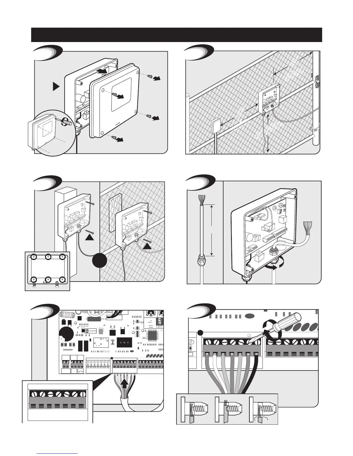
7
Secure wires in terminals.
Insert 7 wires into corresponding color terminals.
Control Box Installation
Remove control box cover.
1
A
Locate control box mounting area. IMPORTANT: Be sure to mount
box at least 3 feet from AC power and 3 feet off the ground.
3’
Min.
4’
Max.
2
Mount control box to post or fence using screws.
4
4”
Feed 4” of opener cable into box through the empty strain relief.
Tighten strain relief nut to secure cable.
Control Box Installation