EasyManua.ls Logo

Milesight UC100 - Page 25

Milesight UC100
31 pages
Print Icon
To Next Page IconTo Next Page
To Previous Page IconTo Previous Page
Loading...
25
Channel ID
Description
00
RS485 (Modbus Master) Channel 1
01
RS485 (Modbus Master) Channel 2
02
RS485 (Modbus Master) Channel 3
...
...
1f
RS485 (Modbus Master) Channel 32
Examples:
1. No Modbus Channel.
ff0bff
Channel
Type
Value
ff
0b (Power On)
ff
2. Fail to fetch Channel1 data.
ff 15 00
Channel
Type
Value
ff
15
00 => Channel 1
3. Succeed to fetch Channel8 data.
ff 19 07 02 03 15 00
Channel
Type
Channel ID
Data Size
Data Type
Value
ff
19
07 =>
Channel 8
02 =>
2 bytes
03 => Hold
16
15 00 =>
00 15 = 21
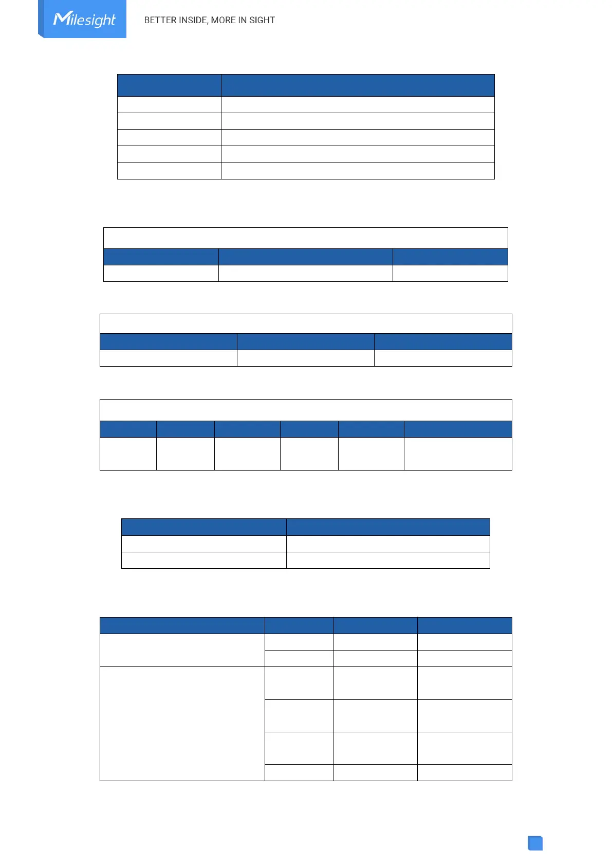
Note: When data type is holding register or input register, ToolBox can set different byte orders.
Take below Modbus register response from RS485 sensors as example:
Register Address
Value (Hex)
0
00 15
1
00 20
When using different byte orders, you can use ToolBox to fetch different results, and the device
will upload data with little endian order.
Data Type
Byte Order
Fetch Result
Uplink (HEX)
Holding/Input Register (INT16)
AB
21 (0x15)
15 00 (BA)
BA
5376 (0x1500)
00 15 (AB)
Holding/Input Register (INT32)
ABCD
1376288
(0x00150020)
20 00 15 00
(DCBA)
CDAB
2097173
(0x00200015)
15 00 20 00
(BADC)
BADC
352329728
(0x15002000)
00 20 00 15
(CDAB)
DCBA
536876288
00 15 00 20

Related product manuals