E
emartinAug 25, 2025
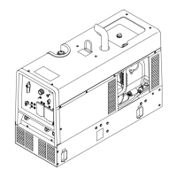
How to fix no weld output on my Miller TRAILBLAZER 302 AIR PAK Welding System?
- GgmirandaAug 25, 2025
To address the issue of no weld output in your Miller Welding System, start by checking the weld control settings and weld connections. Ensure the equipment is disconnected from generator power receptacles during start-up. Increase the front panel and/or remote voltage/amperage control settings. Also, verify and secure connections to the Remote receptacle RC4. If the problem persists, have a Factory Authorized Service Agent inspect the brushes, slip rings, and circuit boards PC1 and PC2.