EasyManuals Logo

Milltronics COMPU-M User Manual

Milltronics COMPU-M
77 pages
To Next Page IconTo Next Page
To Previous Page IconTo Previous Page
Page #17 background imageLoading...
Page #17 background image
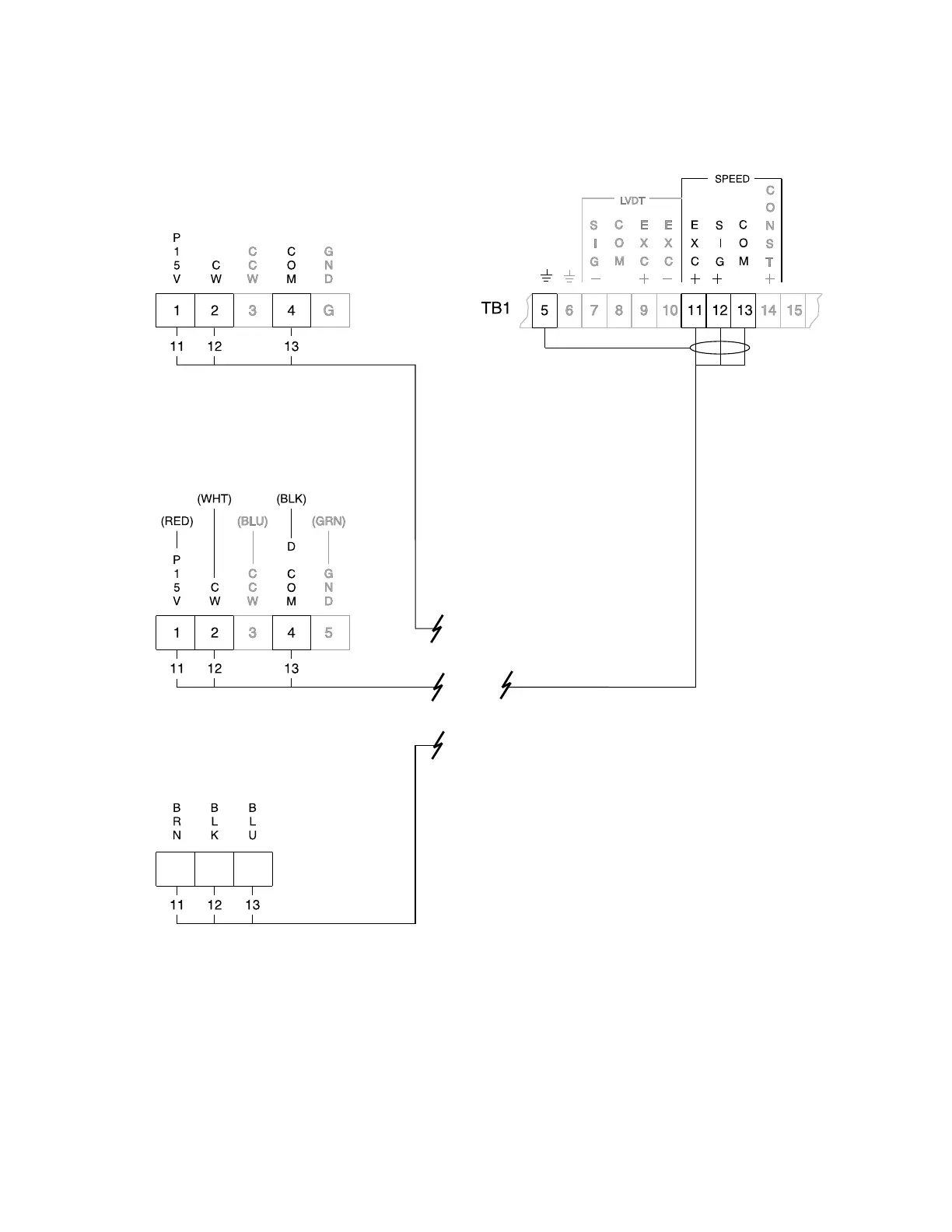
COMPU - M / SPEED SENSOR
INTERCONNECTION
* Connect Compu-M (board B) TB1 - 12 to speed sensor terminal strip:
» position ‘2’ for clockwise speed sensor shaft rotation
» position ‘3’ for counter-clockwise speed sensor shaft rotation.
Speed sensor shaft rotation is viewed from the front cover side of the speed sensor enclosure.
If a speed sensor is not used, a jumper must be connected across Compu-M (board B) TB1 - 13 / 14
MD-36 *
Compu-M
MD-2000 A *
TASS - 3
OR
PL-516 17

Questions and Answers:

Question and Answer IconNeed help?

Do you have a question about the Milltronics COMPU-M and is the answer not in the manual?

Milltronics COMPU-M Specifications

General IconGeneral
BrandMilltronics
ModelCOMPU-M
CategoryControl Systems
LanguageEnglish

Related product manuals