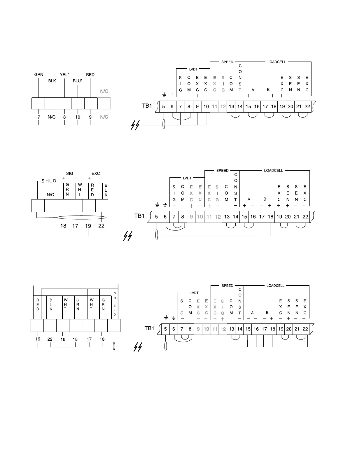
COMPU-M / FLOWMETER INTERCONNECTION
LVDT
SINGLE LOAD CELL
DUAL LOAD CELLS
1. Where a belt scale must be installed in a hazardous area, consult Milltronics or your
distributor for wiring instructions.
2. Where the integrator to load cell belt scale separation exceeds 150 m (500 ft.) :
» A) remove jumpers from Compu-M (board B) TB1 - 19 / 20 and TB1 - 21 / 22
» B) run an additional shielded conductor from each of :
» Compu-M (board B) TB1 - 20 to junction box terminal ‘+ EXC’
» Compu-M (board B) TB1 - 21 to junction box terminal ‘– EXC’
set switch SW1 on board B to ‘Open’
load cell
‘A’
load cell
‘B’
* For connection to an encapsulated LVDT (provided for hazardous environments) YEL = white and BLU = orange.
PL-516 18