• Electrical schematics, pneumatic diagrams (if applicable) and hydraulic diagrams
(if applicable) are located in the electrical and mechanical manual.
Machine specification sheets including travels, tool capacity, etc. are included at the back
of this manual.
Tooling Specifications
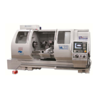
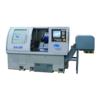
Milltronics lathes come equipped for various tooling sizes depending on machine model
and turret size selected, if any. Please refer to your machine order or dealer to find out
what tooling is required for your particular machine.
The machine may be equipped with a tool turret, tool post, or nothing at all.
Tool holders range from 5/8” x 4”, to 1.25” x 6”, boring bar holders 1” and 1.25”, and for
live tool turrets V40 and V50.
See specifications at the back of this manual for ML35-40 tooling capacities.
16