Pellerin Milnor Corporation 19
WARNING:
Electrified parts inside — can shock or electrocute you.
� Turn off and lockout/tagout electric power before you open an electri-
cal cabinet.
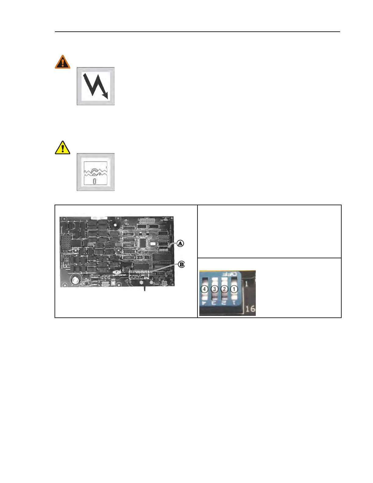
The microprocessor board holds the DIP switches as shown in the following figure also shows
the on and off positions. Set the switches to the desired positions according to the following table.
Turn the machine on; the display will show the current configuration.
CAUTION: Risk of improper configuration — On some machines, the processor
board is installed in the control box so that the labels printed on the DIP
switch appear inverted.
� Do not assume that the switch is right side up. Always reference the la-
bels (OFF, ON, 1, 2, etc.) printed on the switch when setting DIP
switches.
Figure 9. Location of DIP Switches
Processor Board
Legend
A. DIP switch
B. Board identification area
1. OFF
2. ON
3. ON
4. OFF
DIP Switch (Partial View)
Programming