Pellerin Milnor Corporation iii
4.1.7 Viewing Inputs and Outputs During Operation.....................................................71
4.1.8 Viewing Water Level and Temperature Data During Operation ...........................72
4.2 Error Messages ................................................................................................................72
4.2.1 Error Messages at Power Up .................................................................................72
4.2.2 Error Messages during Normal Operation ............................................................73
5 Supplemental Information ...........................................................................................................76
5.1 The E-P Plus
®
and E-P Express
®
Hardware ....................................................................76
5.1.1 Keyswitches...........................................................................................................76
5.1.1.1 Run/Program Keyswitch ............................................................................76
5.1.1.2 Automatic/Test Keyswitch (E-P Plus
®
Models Only)................................76
5.1.2 Display...................................................................................................................76
5.1.3 Power Supply.........................................................................................................76
5.1.4 CPU Processor Board ............................................................................................77
5.1.5 Outputs ..................................................................................................................77
5.1.6 Option Outputs (E-P Plus
®
Models Only).............................................................78
5.1.7 Temperature Probe (E-P Plus
®
Models Only).......................................................78
5.1.8 Pressure Sensor (E-P Plus
®
Models Only) ............................................................78
5.2 Serial Memory Storage Device Applications ..................................................................78
5.3 Construction of External Serial Link Cables ...................................................................80
5.3.1 Pin Identification ...................................................................................................81
5.3.2 How to Wire the Cables.........................................................................................82
5.3.2.1 Cable Specifications ...................................................................................82
5.3.2.2 Connecting Two or More Machines for Machine-to-machine
Transfer...................................................................................................82
5.3.2.3 Connecting a Machine to a Serial Memory Storage Device ......................83
5.4 Printer Requirements and Settings ..................................................................................84
5.4.1 Cable Requirements...............................................................................................84
5.4.2 Configuring the Citizen GSX-190 Printer.............................................................85
5.4.3 Configuring the Epson LX300 Printer ..................................................................85
5.4.4 Previous Printer Models ........................................................................................86
Figures
Figure 1 How Rotating Forces Act On the Foundation ............................................................6
Figure 2 Incorrect Configurations That Let the Chemical Supply Go In the Ma-
chine by a Siphon........................................................................................................8
Figure 3 Incorrect Configurations That Let the Chemical Supply Go In the Ma-
chine by Gravity..........................................................................................................9
Figure 4 Examples of Manifolds for Chemical Tubes. Your equipment can look
different.......................................................................................................................9
Figure 5 A Configuration that Prevents Flow in the Machine When the Pump is
Off (if the chemical tube and tank have no pressure) ...............................................10
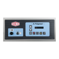
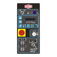
Figure 6 Typical Control Panels..............................................................................................15
Figure 7 Location of DIP Switches .......................................................................................19
Figure 8 Controls Identification on Serial Memory Storage Device ......................................49
Figure 9 Processor Board ........................................................................................................66
Figure 10 Level Sensor Testing Fixture ....................................................................................69
Figure 11 Pressure Transducer Component Identification........................................................71
Contents
 Loading...