Pellerin Milnor Corporation 81
5.3.1 Pin Identification
BNCUUP02.C02 0000196983 C.2 A.9 1/2/20 1:30 PM Released
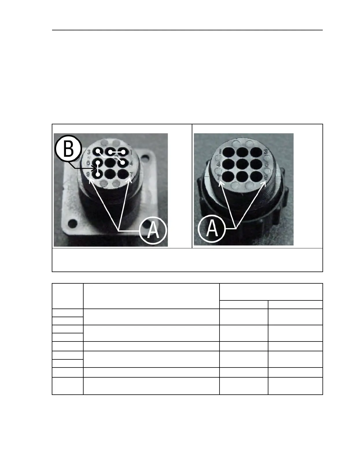
Figure 14: 9-Pin DIN Connector Pin Identification (from wire entry side of connectors), page 81
illustrates the DIN receptacle (which uses male pins) and the mating plug (which uses female pin
sockets), each viewed from the wire entry side. The receptacle is normally installed and wired at
the Milnor factory. The plug and female pin sockets for customer use are provided in a bag inside
the electric box. Table 16: External Serial Link Pin Assignments, page 81 shows the function of
each pin.
Figure 14. 9-Pin DIN Connector Pin Identification (from wire entry side of connectors)
Receptacle (uses male pins)
Plug (uses female pin sockets)
Legend
A...Pin numbers molded into parts
B...Heavy white lines terminated with dots indicate pins normally connected together at the Milnor factory
Table 16. External Serial Link Pin Assignments
Pin
Number Function
Receptacle Wiring (inside electri-
cal enclosure)
Wire Number Color Code
1
Serial low DLL Blue and black
2
3
Serial high
DLH Blue and red
4
5
Clear to send (not used on these models)
CTS
Blue and orange
6
Electronic ground
2G Blue and white
9
7
Transmit data (not used on these models)
TXD
Blue and orange
8
+5 volts DC (used for serial memory storage
device only)
V1 Blue
Supplemental Information


 To Next Page