© 2009 MIMAKI ENGINEERING CO.,LTD.
6.2.3 P.2
6.2.3 Mounting of Head Unit
1
2
3
4
5
6
7
8
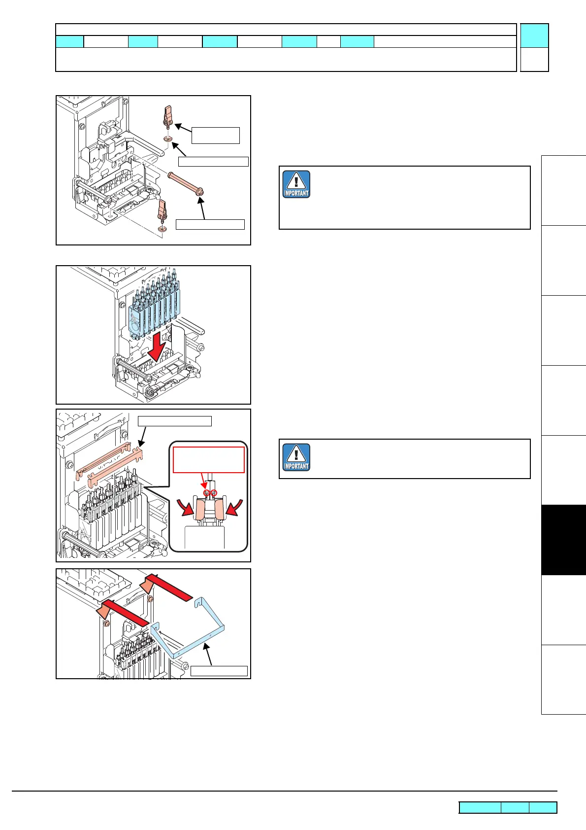
5. Pay attention to the direction of the AD locking spacer and
tighten the left and right AD locking levers.
Left: Set the depression towards the front.
Right:Set the depression sideways.
6. Mount the right head lock screw.
7. Insert the pressure damper SP assy in the order described on
the tab.
8. Mount the damper lock SP from a recess.
9. Mount the P cover BKT and tighten the right and left screws.
10. Connect the head FFC assy and head memory cable assy to the
ink slider PCB assy.
AD Locking
Lever
Head Lock Screw
AD Locking Spacer
Tighten the AD locking lever to a certain degree and
go it down for locking.
At this time, if tightened too weakly, the lever cannot
be locked, and if it is tightened too strongly, the AD
locking spacer may crack. Proceed carefully with work.
Damper Lock SP
This is used as a
supporting point for
mounting from a recess.
If the connection of the damper is loosened, the
damper lock will not work. Make sure that no loose
connection exists.
R.1.0
Maintenance Manual > Disassembly and Reassembly > Ink-related Parts > Mounting of Head Unit
Model CJV30/TPC Issued 2008.08.04 Revised F/W ver. 1.00 Remark
1.0

 Loading...


