© 2009 MIMAKI ENGINEERING CO.,LTD.
6.5.4 P.1
1
2
3
4
5
6
7
8
R.1.0
Maintenance Manual > Disassembly and Reassembly > Electrical Parts > Head Memory PCB Assy
Model CJV30/TPC Issued 2008.08.04 Revised F/W ver. 1.00 Remark
1.0
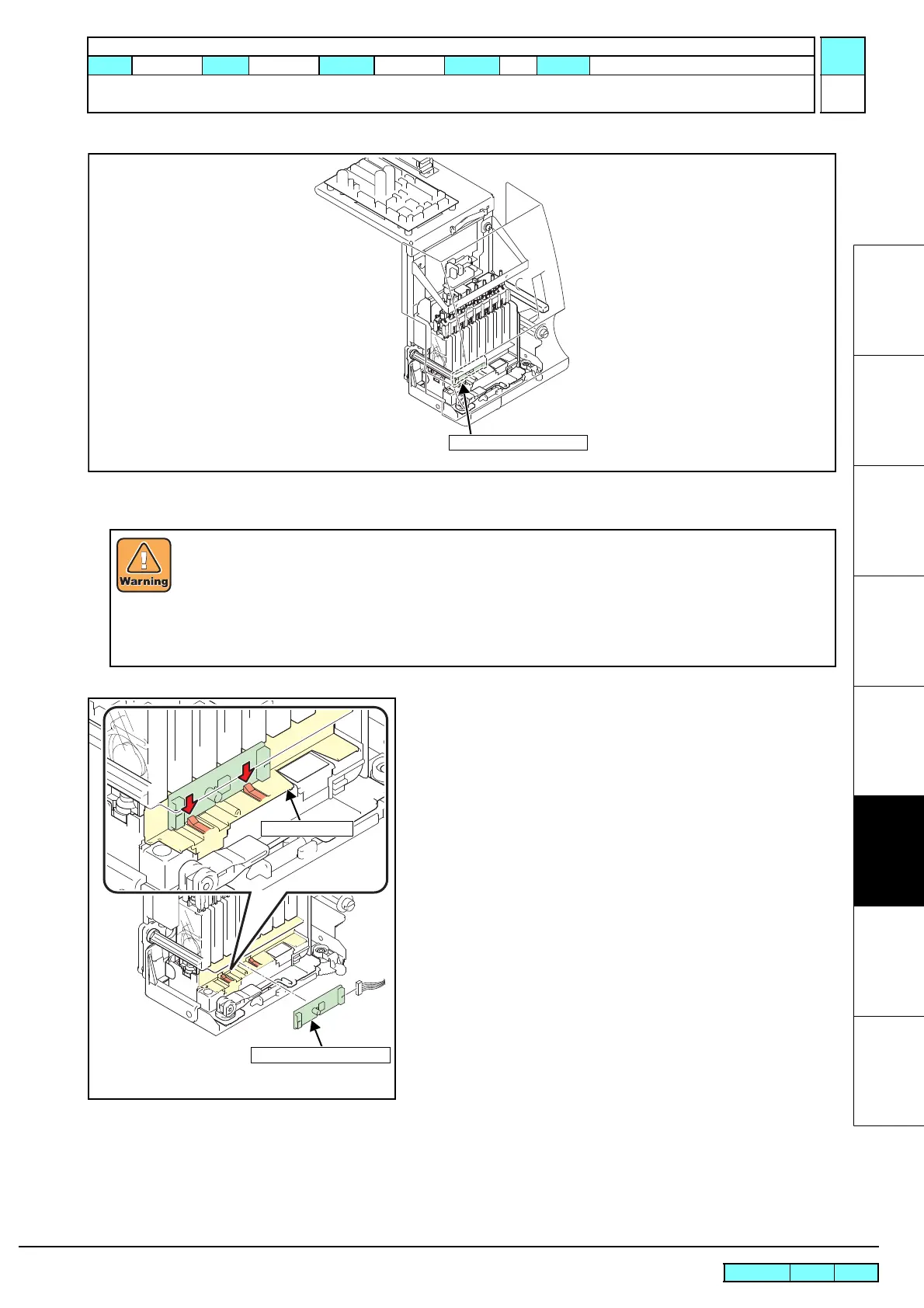
6.5.4 Head Memory PCB Assy
Work procedures
1. Remove the following covers.
• Front Cover
• Print Head Cover
2. Move the head unit on the platen.
3. Release the hook of the ID PCB cover, remove the head
memory PCB assy and then disconnect all the cables.
4. Reverse the disassembly procedure for reassembly.
After turning off the sub and main power switches in order, unplug the power code.
Check if no electric charge is remaining in the PCB.
Refer to the "4.5.2 Electric charge checking when replace the Electrical Parts"
It is very dangerous if sleep mode functions mistakenly during the operation.
Moreover, the PCB may be damaged in case electric charge still remains inside.
Also there is a possibility of electric shock because of high power voltage applied the high-pressure part
of the power supply PCB assy. Take care to avoid contact with it.
ID PCB Cover
Head Memory PCB Assy

 Loading...


