© 2009 MIMAKI ENGINEERING CO.,LTD.
7.1.2 P.5
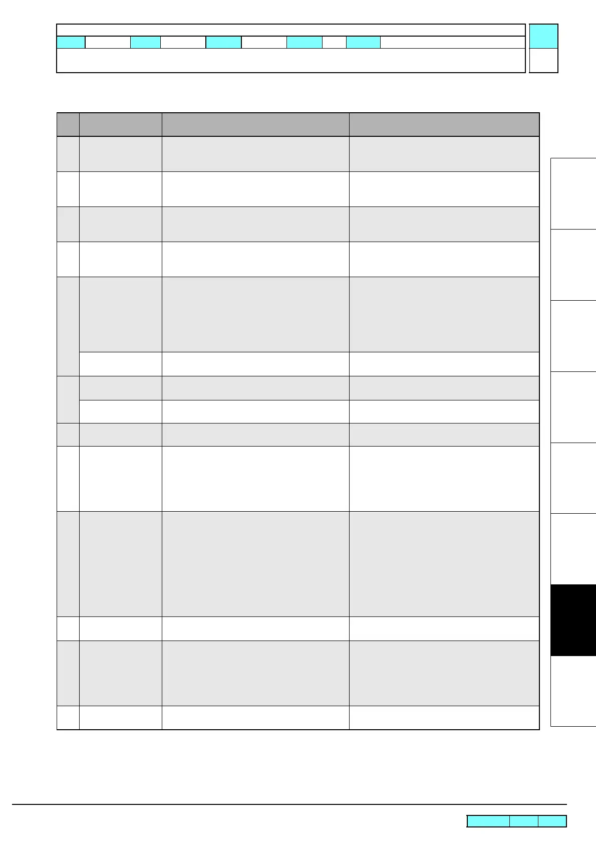
7.1.2 List of Error Messages
1
2
3
4
5
6
7
8
ERROR COMMAND
(This does not occur during the customer use.)
1. Check the USB cable.
(specifications, cable length, etc.)
ERROR PARAMETER
(This does not occur during the customer use.)
1. Check that PRM file and parameter data
correspond to version of the printer.
ERROR DATA
(This does not occur during the customer use.)
1. Check the USB cable.
(specifications, cable length, etc.)
ERR PRM.SHORTAGE
(This does not occur during the customer use.)
1. Check that PRM file and parameter data
correspond to version of the printer.
170
ERROR 170
CUTTER LOCK
The cutter head cannot be fixed in the standby
position, and connector changeover cannot be
made.
Turn off the main power, and turn it on a little later.
1. Set cut system parameter No. 37 “CLKAJST”
to “0” and turn power on.
2. Check the operation of the C connecting hook
or replace it.
3. Check the operation of the change lever or
replace it.
ERROR 170
PRINT HEAD LOCK
The print head cannot be fixed in the standby posi-
tion, and connector changeover cannot be made.
Check the operation of the P head connecting hook
or replace it.
180
ERROR 180
CUTTER JOINT
The cutter head or the connector came off during
the operation.
Check the vicinity of the connection magnet or
replace it.
ERROR 180
PRINT HEAD JOINT
The print head or the connector came off during the
operation.
Turn off the main power, and turn it on a little later.
181
ERROR 181
PR POSITION
Media could not be detected.
(The location of the pinch roller is not appropriate.)
Set the pinch roller in the proper place.
200
ERROR 200
HEAD MEMORY (----)
An error occurred in head unit memory. Turn off the main power, and turn it on a little later.
If the error occurs again, carry out the followings.
1. Check the head memory cable.
2. Replace the head memory.
3. Replace the ink slider PCB assy. (See 6.5.9)
4. Replace the main PCB assy. (See 3.4.1)
202
ERROR 202
DEVICE CONSTRUCTION
Head unconnected.
FFC broken or poor connection.
An error occurred in head unit memory.
Turn off the main power, and turn it on a little later.
If the error occurs again, carry out the followings.
1. Refer to 7.2.3 Electrical Troubleshooting, and
replace the following parts if it has damaged.
•.Check the head and head FFC cable.
•.Check the HDC FFC cable.
•.Replace the ink slider PCB assy. (See 6.5.9)
•.Replace the main PCB assy. (See 3.4.1)
2. Check the head memory cable.
3. Replace the head memory.
203
ERROR 203
SDRAM SIZE
The printer is not provided with the required size of
SD-RAM.
Turn off the main power, and turn it on a little later.
205
ERROR 205
47V HEAD VOLTAGE
An excessive current flowed in the 47 V circuit of
the print head, thus the fuse was blown.
Refer to Electrical Troubleshooting ( See 7.2.3 ),
and replace the following parts if it has damaged.
1. Replace the head FFC and HDC FFC cable.
2. Replace the head.
3. Replace the fuse. (Main PCB F13)(See 6.5.17)
4. Replace the main PCB assy. (See 3.4.1)
206
ERROR 206
MAIN PCB
The installed main PCB is not the one for CJV. Replace the main PCB with the one for exclusive
use with CJV.
List of error messages (5/6)
Error
No.
Indication on LCD Cause Remedy
R.1.2
Maintenance Manual > Troubleshooting > Details on Errors and Malfunctions > List of Error Messages
Model CJV30/TPC Issued 2008.08.04 Revised 2009.06.30 F/W ver. 1.20 Remark
1.2

 Loading...


