© 2009 MIMAKI ENGINEERING CO.,LTD.
2.3.4 P.1
1
2
3
4
5
6
7
8
R.1.0
Maintenance Manual > Electrical Parts > Circuit Board Specifications > Regenerative Resistivity PCB Assy
Model CJV30/TPC Issued 2008.08.04 Revised F/W ver. 1.00 Remark
1.0
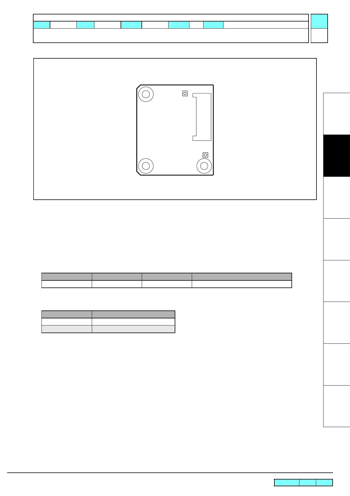
2.3.4 Regenerative Resistivity PCB Assy
Outline
Board name: Regenerative Resistivity PCB Assy
Is located on the main PCB assy inside the electrical box.
Controls counter electromotive voltage by supplying the electrical power to the motor via this PCB.
List of connectors
Test poi nt
CN No Pin Connected to: Remarks
CN1 10 Main PCB Assy Power supply to the X and Y-axis motors
Terminal name Application
TP1 +42V
TP2 Power supply voltage of the motor
TP2
TP1
CN1

 Loading...


