© 2009 MIMAKI ENGINEERING CO.,LTD.
2.3.9 P.1
1
2
3
4
5
6
7
8
R.1.0
Maintenance Manual > Electrical Parts > Circuit Board Specifications > Cutter Slider PCB Assy
Model CJV30/TPC Issued 2008.08.04 Revised F/W ver. 1.00 Remark
1.0
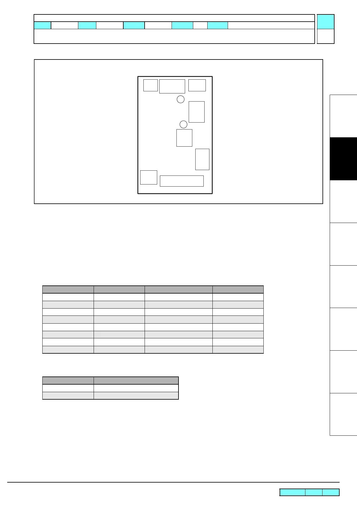
2.3.9 Cutter Slider PCB Assy
Outline
Board name: Cutter Slider PCB Assy
Is located on the top of the head part slider.
FFC from cutter driver PCB assy is connected to this PCB to relay signals to pen head.
Connecting sensor, mark sensor, auto cutter blade, etc. are connected to this PCB.
List of connectors
Test poi nt
CN No Pin Connected to: Remarks
CN1 17 Cutter Driver PCB Assy IO
CN2 4 Mark Sensor
CN3 2 Pen Solenoid
CN4 3 Connecting Sensor
CN5 2 LED Pointer
CN6 3 Auto Cutter Blade Solenoid
CN7 3 PR Sensor
CN8 2 PR Switch Solenoid
Terminal name Application
TP1 Output voltage of mark sensor
TPG1 GND
CN1
CN3
CN2
CN7
CN4
TP1
TPG1
CN8
CN6
CN5

 Loading...


