© 2009 MIMAKI ENGINEERING CO.,LTD.
2.3.13 P.1
1
2
3
4
5
6
7
8
R.1.0
Maintenance Manual > Electrical Parts > Circuit Board Specifications > Take-up PCB Assy
Model CJV30/TPC Issued 2008.08.04 Revised F/W ver. 1.00 Remark
1.0
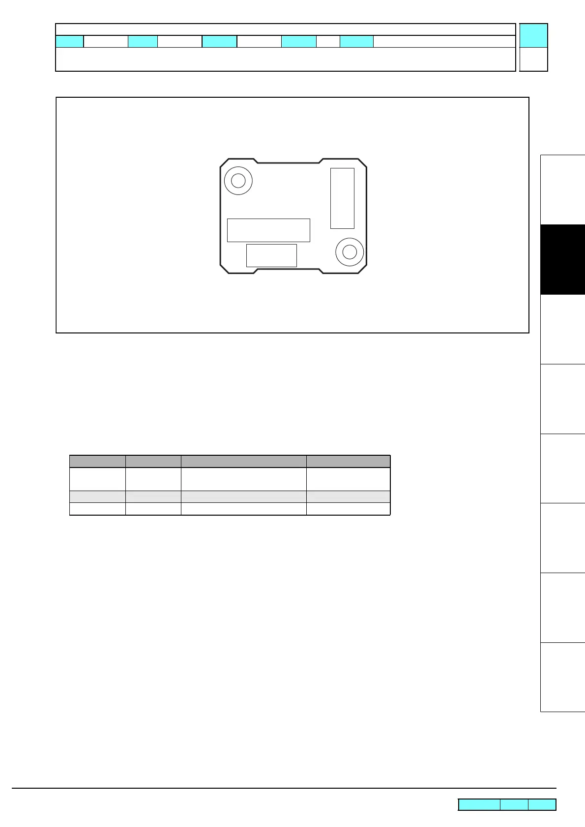
2.3.13 Take-up PCB Assy
Outline
Board name: Take-up PCB SK Assy
This PCB is connected to the station PCB assy via external connector, which can be attached or removed by users. It
is used inside the take-up motor unit, as a junction between the station PCB assy and take-up motor.
List of connectors
CN No Pin Connected to: Remarks
CN1 9 External Connector Cable
(Station PCB Assy)
Power source
CN2 5 Start, direction changing switch
CN3 6 Take-up Motor
CN3
CN1
CN2

 Loading...


