2-14
DVI Interface Board
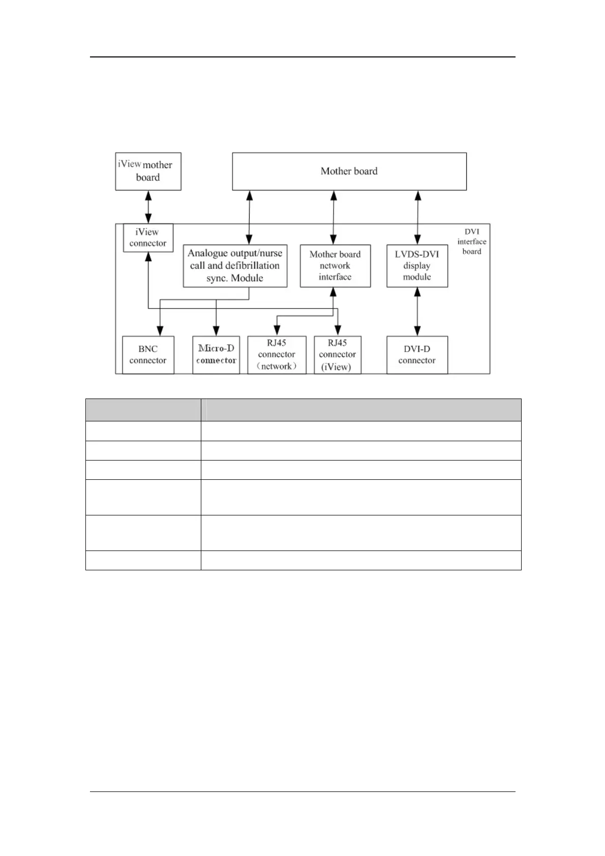
The DVI interface board is connected with the mother board and the iView mother board.
The following diagram shows its interfaces to other components.
Interface Description
iView Connector Connects the iView mother board.
BNC connector Outputs nurse call signals.
Micro-D connector Outputs analog signals and defibrillator synchronization signals.
RJ 45 connector
(network)
It is a standard RJ45 connector, providing 10/100 BASE-TX Ethernet
communications channels. It connects an Ethernet network or a PC.
RJ 45 connector
(iView)
It is a standard RJ45 connector for connecting a iView network.
DVI-D connector Connects a secondary display.
CF Card assembly
The CF assembly serves the non-volatile CF storage card which is used for data storage and
transfer. It is connected with the mother board.
Internal wireless network card
The internal wireless network card connects with the mother board. User can set network
type as LAN or WLAN through user interface and can set the internal wireless network card
through PC.