3-22
3 Blow to the CO
2
sensor to generate a CO
2
waveform and then place the sensor in the air.
Check if the alarm message [CO
2
Apnea] is displayed on the screen.
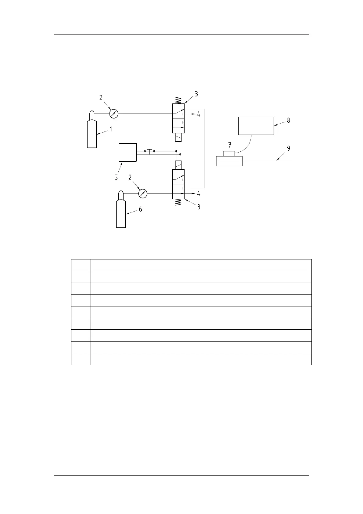
4 Connect the test system as follows
Indication of numbers in the figure above
1 A steel gas cylinder with 6±0.05% CO
2
2 Flowmeter
3 3-way valve (power supply controlled)
4 Open to air
5 Power supply (controlling two 3-way valves)
6 Compressed air or N
2
with standard concentration
7 Mainstream CO
2
sensor
8 Patient monitor
9 Tube (preventing back flow)
5 Adjust the power supply and turn on/off 3-way valves to ensure that that only one
cylinder is connected to Mainstream CO
2
sensor via 3-way valves at one time and the
flowmeter reading is stable and within 2-5L/min.
6 Switch between the two cylinders to connect Mainstream CO
2
sensor at intervals of 6
-10s and check if the displayed CO
2
value is within 6±0.05%.