Structure and Assembly/Disassembly 7-47
Figure 7-53 Disassemble the cable of the main unit (part 1)
5. Remove the screws M4 X 12 (2 pcs) of decorative cover of the keyboard, and pull
the cable out of the decorative cover. Then, remove it.
Figure 7-54 Disassemble the cable of the main unit (part 2)
6. Remove IO assembly and the rear cover(refer to 7.4.2 IO Rear Board and 7.4.3
Machine Fan).
7. Remove the ground wire screws, and cut the strapping off with diagonal cutting
pliers.
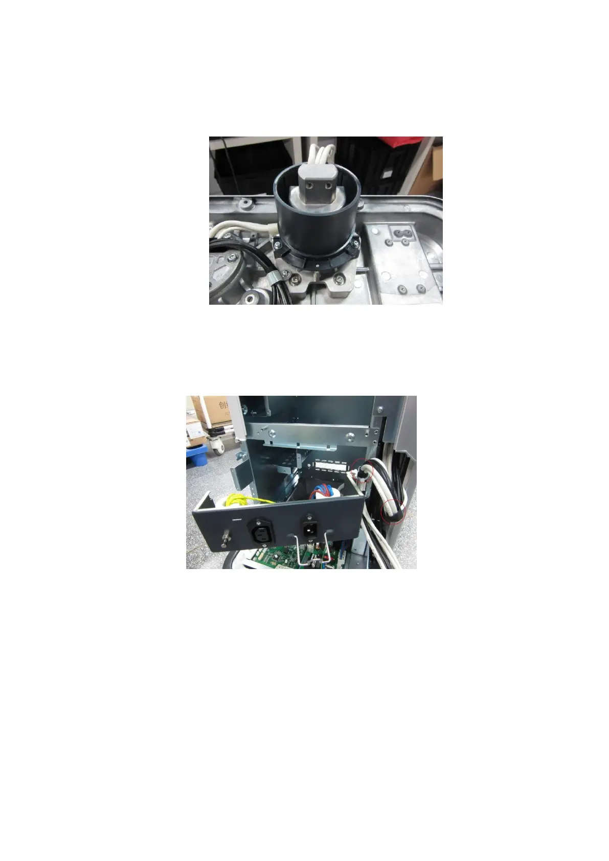
Figure 7-55 Disassemble the cable of the main unit (part 3)
8. Rotate to remove the power input assembly (refer to Chapter 7.4.4 ).
9. Unplug the cable related to the cable of main unit. Open the square cable clip to pull
out the cable.