7-48 Structure and Assembly/Disassembly
Figure 7-56 Disassemble the cable of the main unit (part 4)
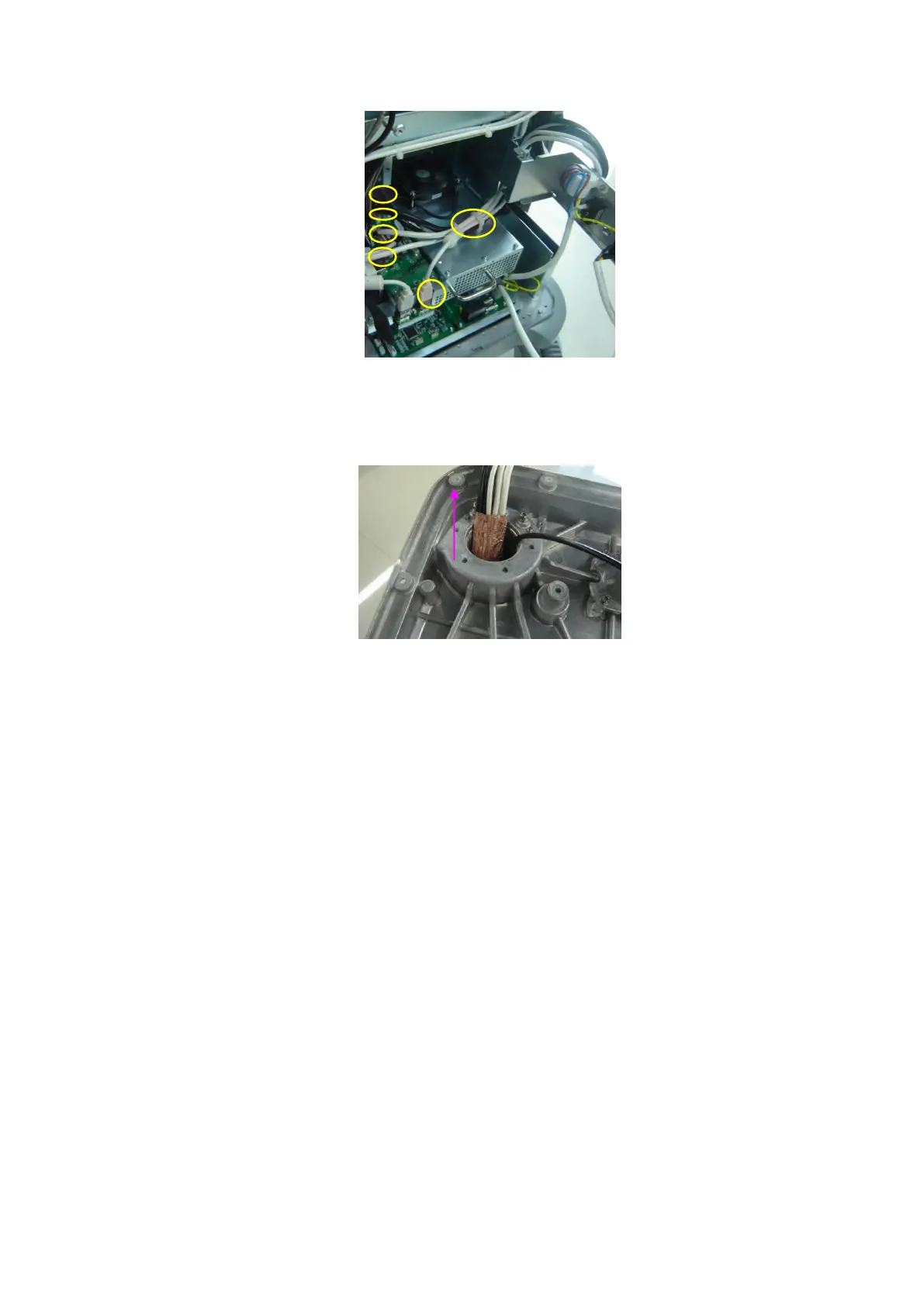
10. Pull the cable of main unit out of the bottom of the keyboard slowly.
Figure 7-57 Disassemble the cable of the main unit (part 5)
7.4.12.3 Isolation Transformer
1. Remove the IO module and the rear cover (Refer to chapter 7.4.2 IO Rear Board and
7.4.3 Machine Fan).
2. Remove or rotate to the right to open the power input assembly (refer to step 2 in
7.4.5 Power Module Assembly).
3. Remove the power module assembly and main unit box assembly (Refer to 7.4.5
Power Module Assembly).
4. Remove the main unit assembly (refer to 7.4.6 chapter).
5. Remove the M5X10 inner hex head screws (4 pcs, 2 at the front side, and 2 at the
rear side) fixing the isolation transformer, the flat washer and elastic washer, and
then take out the isolation transformer.