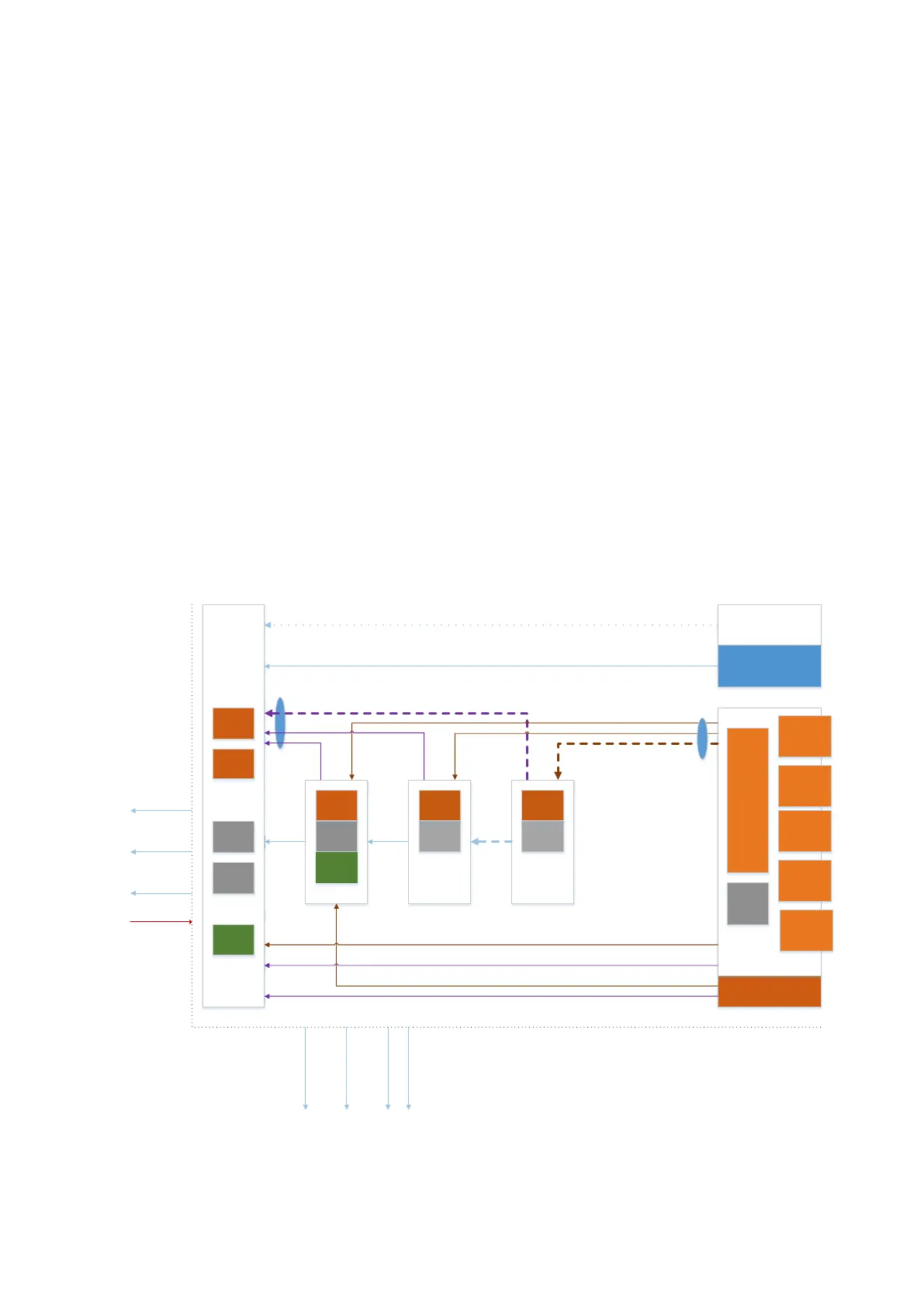
4-2 Product Principle
⚫ The management functions of the probe decouple the transmitting/receiving channel, and
communicate with the engine board.
⚫ As the independent sub-module, 4D driving function and physiological signals are
subordinate to the engine board.
⚫ As an option, CW receiving function can be realized through an independent single board
and is subordinate to TRA board signal.
◼ Back-end unit: more functions are achieved on back-end unit. It basically resembles with PC. It
is equipped with main functions of the main unit, calculation capacity of image post-process,
operator-system interface to human-computer interaction, etc. PC module takes charge of
back-end unit. The elements are shown above.
◼ Power supply unit: it supplies the power to the front-end unit, back-end unit and peripherals.
Other elements are shown above.
⚫ PHV board
⚫ DC-DC board
⚫ Battery * 2
⚫ Battery connecting board
⚫ 24V to 12V Power Conversion board
⚫ AC-DC Module
⚫ AC connecting board
4.2 Ultrasound Front-end Unit