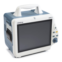
2-18
Battery Control Circuit
When the AC voltage and batteries coexist, this circuit controls the process of charging the
batteries with the DC voltage converted by the AC/DC part. When the AC voltage is unavailable,
this circuit controls the batteries to supply power for the subsequent circuits.
5V DC/DC
This part converts the DC voltage to the stable 5V DC voltage and supplies it for the external
boards.
12V DC/DC
This part converts the DC voltage to the stable 12V DC voltage and supplies it for the external
boards.
Power Switch Circuit
This circuit controls the status of the 5V DC/DC part and the 12V DC/DC part, thus to control
the switch of the patient monitor.
Voltage Detect Circuit
This circuit detects the output voltages of the circuits, converts the analog signal to the digital
signal, and sends the digital signal to the main board for processing.