2-19
2.3 Software Description
2.3.1 General
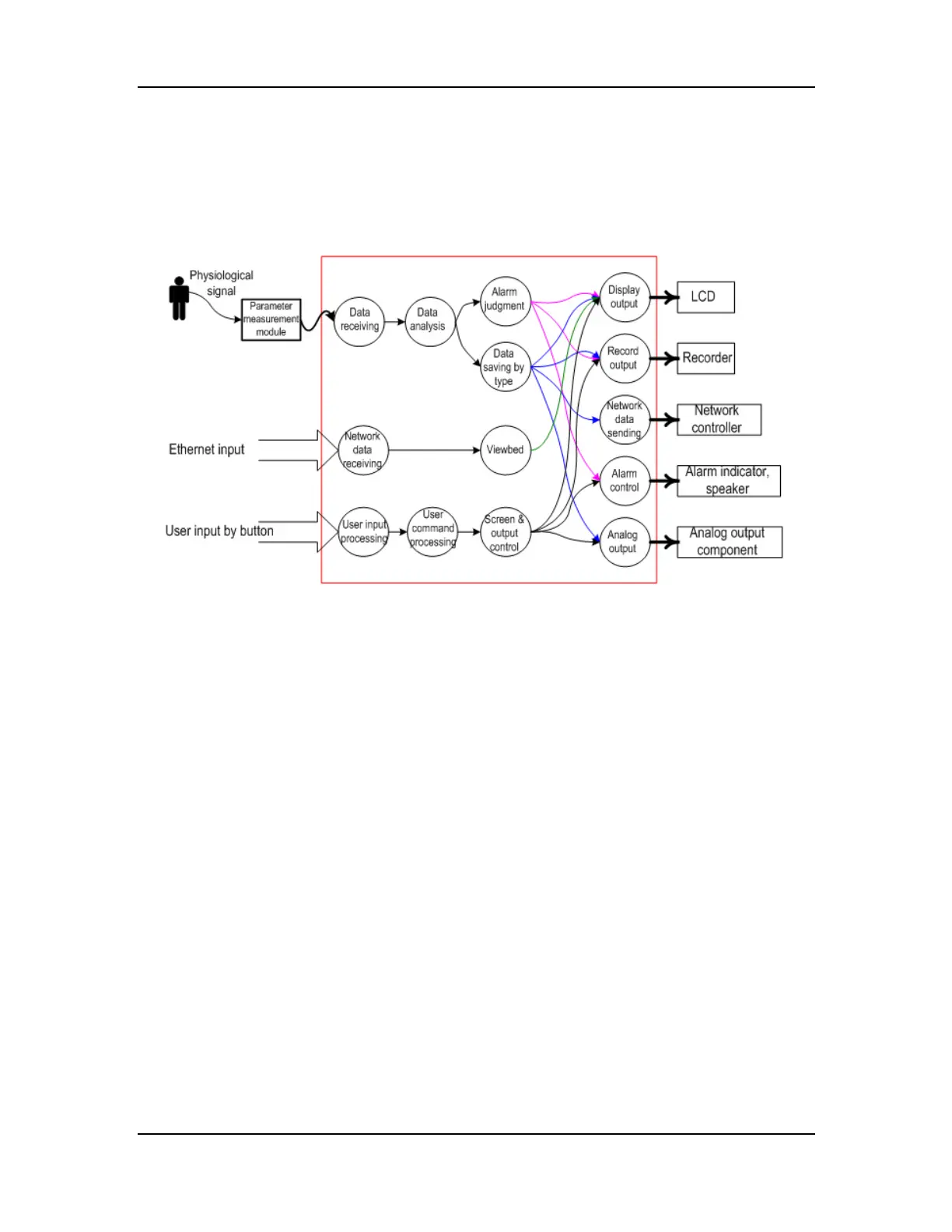
Figure 2-12 System function
As shown in Figure 2-12, in the red frame is the software system, on the left to the red frame are
the inputs of the software system, and on the right to the red frame are the outputs. The parameter
measurement module exchanges data with the software through the serial port, while the user
interacts with the system through the button panel. Among the output devices, the recorder and
alarm device receive data through the serial ports, the analog output component is an MBUS
component, and the LCD and network controller are controlled directly by CPU.