Image Optimization 5-49
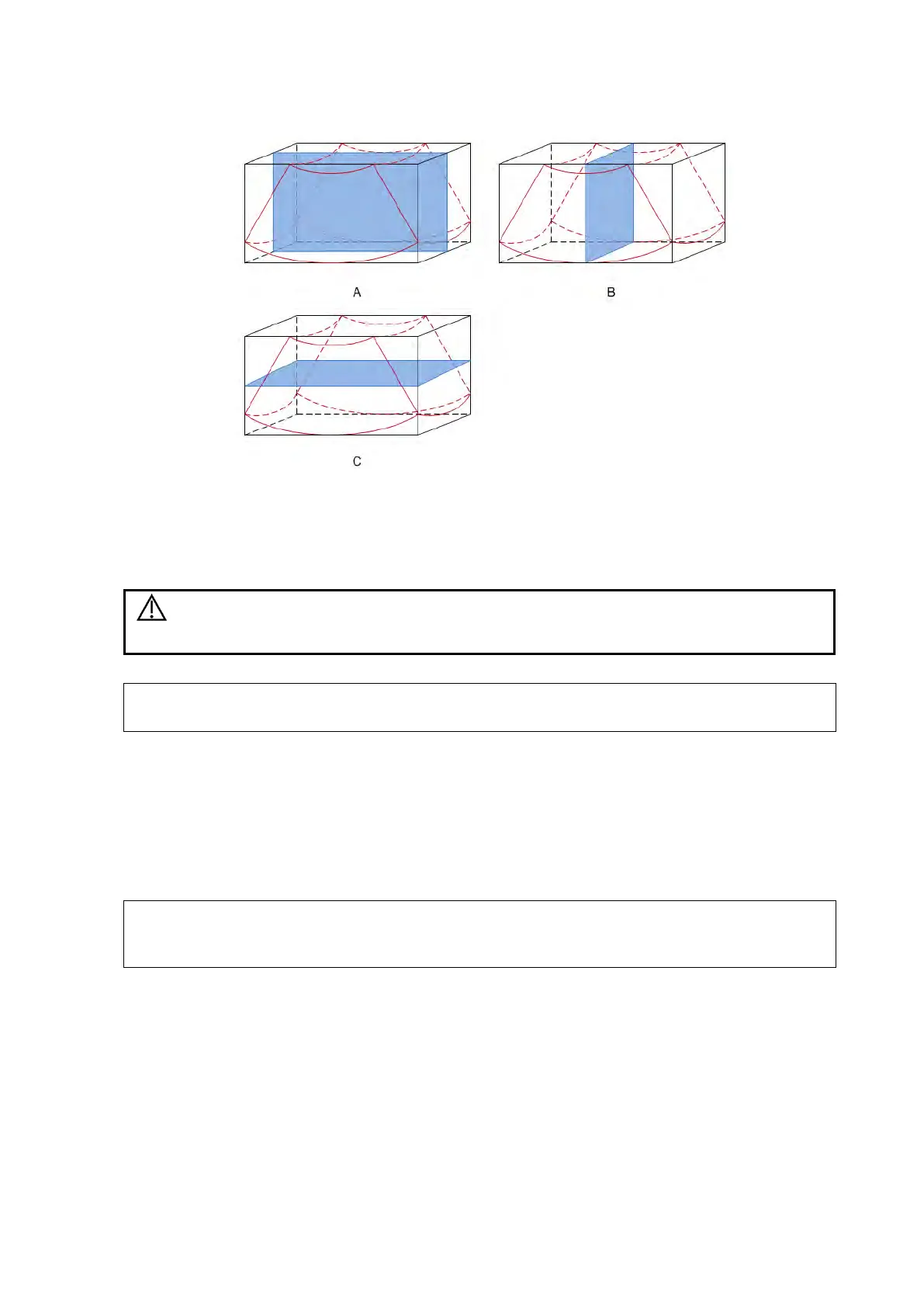
A, B and C sectional images correspond to the following sections of the 3D image.
Section A: corresponds to the 2D image in B mode. Section A is the sagittal section, as
shown in Figure A above.
Section B: is the horizontal section, as shown in Figure B above.
Section C: is the coronal section, as shown in Figure C above.
Ultrasound images are provided for reference only, not for confirming
diagnoses. Use caution to avoid misdiagnosis.
In accordance with the ALARA (As Low As Reasonably Achievable) principle, try to
shorten the sweeping time after a good 3D image is obtained.
5.15.2 Smart 3D
The operator manually moves the probe to change its position/angle when performing the scan.
After scanning, the system carries out image rendering automatically, then displays a frame of the
3D image.
Smart 3D is an option.
Linear probes support Smart 3D imaging.
In Smart 3D image scanning, if the probe orientation mark is oriented to the operator’s
finger, perform the scan from right to left in linear scan, or rotate the probe from left to
right in rocked scanning. Otherwise, the VR direction will be wrong.
5.15.2.1 Basic Procedures for Smart 3D Imaging
To perform Smart 3D imaging:
1. Select the appropriate probe and exam mode. Make sure there is sufficient gel on the probe
for scanning.
2. Obtain a 2D image.
3. Tap [Smart 3D] on the right side of the operating panel to enter Smart 3D acquisition
preparation mode, and define the ROI as well as the curved VOI.
To adjust the ROI: