minnkotamotors.com | 13
©2018 Johnson Outdoors Marine Electronics, Inc.
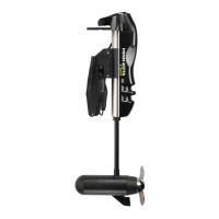
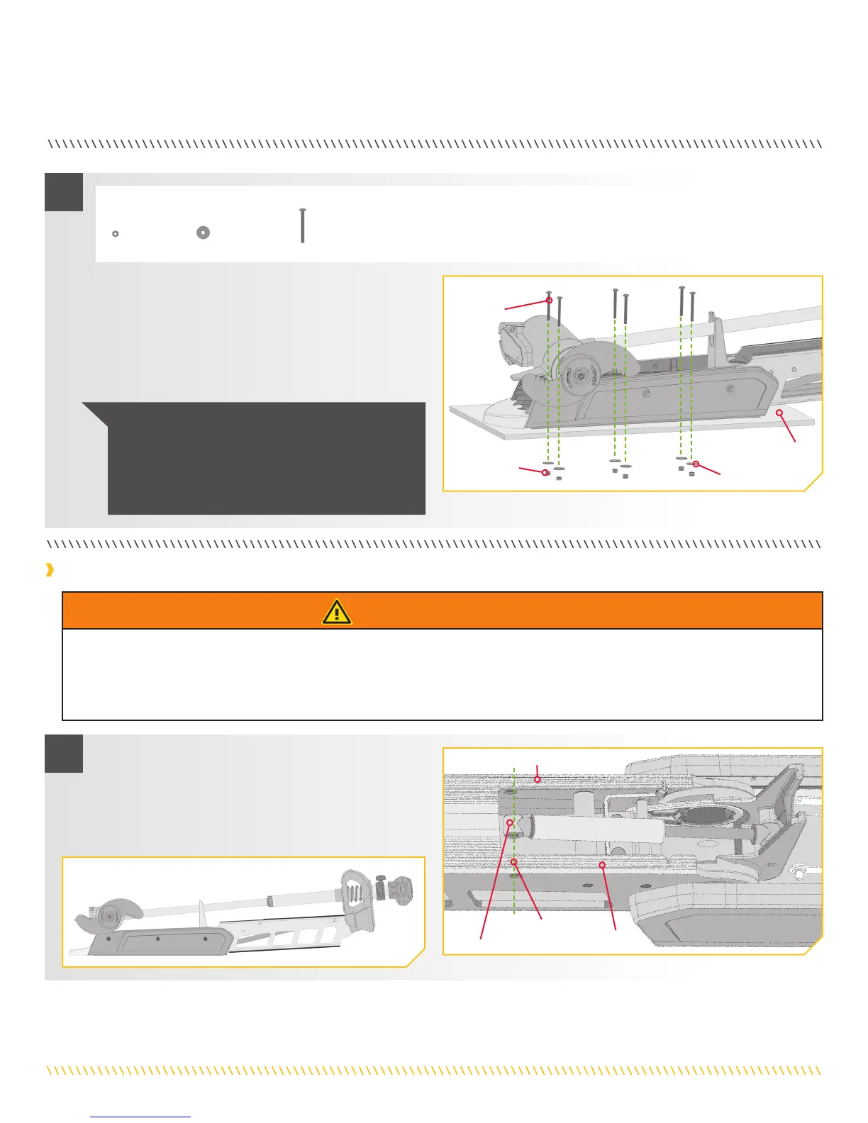
INDEXING THE MOTOR
a. Position the motor to the stowed position with the
Pull Grip and Rope to disengage the latch bar,
allowing the motor to fold into a flat position.
b. Once in the stowed or flat position, the Gas Spring
Pin and Spacers can be installed.
Gas Spring Cylinder
Proper Alignment
Outer Arm
Outer Arm
k. Put a 1/4-20 x 2 1/2" Screw (Item #4) in each of the
drilled locations. The Screw should pass through the
Mount Plate and the boat deck.
l. Place a Flat Washer (Item #5) and then a Nylock Nut
(Item #6) at the end of each screw as shown and
secure. Make sure all hardware is secure.
ITEM(S) NEEDED
#5 x 6
Screw
Deck
Flat Washer
Nylock Nut
5
#6 x 6
#4 x 6
NOTICE: To prevent seizing of the stainless steel
hardware, do not use high speed installation tools.
Wetting the screws or applying an anti-seize may
help prevent seizing. If possible, secure all sets of
mounting bolts, nuts and washers.
Installing the Gas Spring Pin
WARNING
The gas assist lift mechanism in this unit is under high spring pressure when the motor is in the deployed position. Do not remove
the Bowguard from the mount without disconnecting one end of the gas spring. Failure to do this can create a condition where
accidental pulling of the Pull Grip and Rope may cause the mount to spring open rapidly, striking anyone or anything in the direct
path.
1
 Loading...