 Loading...
Do you have a question about the MINN KOTA FORTREX and is the answer not in the manual?
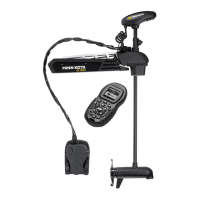
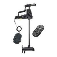
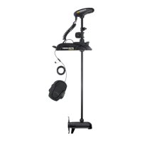
| Thrust | 80 lbs |
|---|---|
| Shaft Length | 45 inches |
| Max Amp Draw | 56 Amps |
| Speed Control | Variable |
| Blade Material | Composite |
| Motor Technology | Digital Maximizer |
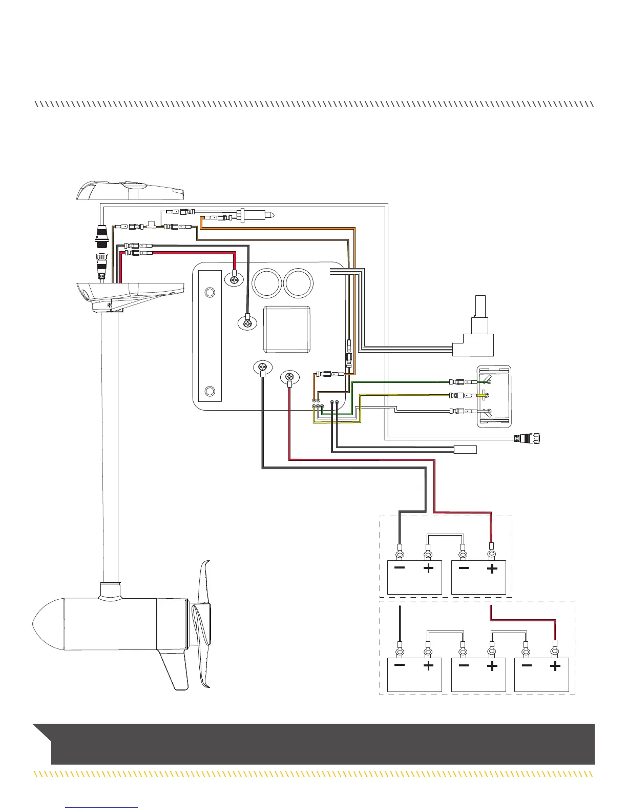
| Voltage | 24V |
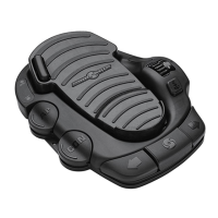
| Control Type | Cable Steer Foot Pedal |
| Mount Type | Bow |
| Type | Trolling Motor |
| Battery Requirement | 2 or 3 deep-cycle batteries |
| Warranty | 2 years |