Remove the middle case from the lower case: it is necessary to remove the screw in the upper left corner of the middle
case.
4.3. PCBs and components
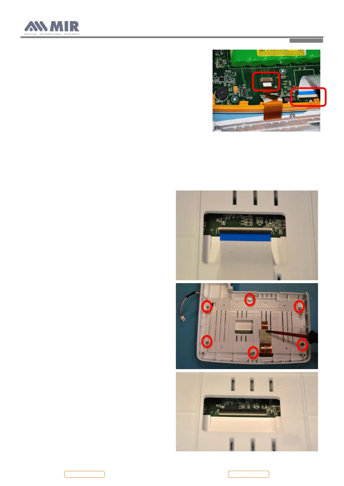
4.3.1. Removing and replacing the display
Open Spirolab as described in Paragraph 4.2.1; remove the
damaged display from the upper casing. First of all remove
the white flat cable from the connector on the rear side of
the display (see image), then remove the nuts and the
washers from the upper case.
Now the damaged display can be removed from the case.
Apply a new one paying attention to insert the red and
white cable in the hole. Apply the nuts and the washers to
the screws
Check if the display is aligned with the housing and then
close firmly the nuts.
Insert the white flat in the connector and make sure that the
black part of the connector is firmly closed above the flat.
Apply a bit of hot glue to the connector to block the
opening of it.
 Loading...